Projects
Search and Rescue?
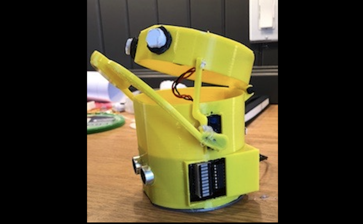
Kicker Bot
Loopholes galore.
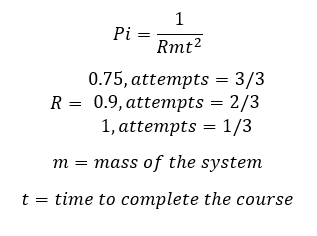
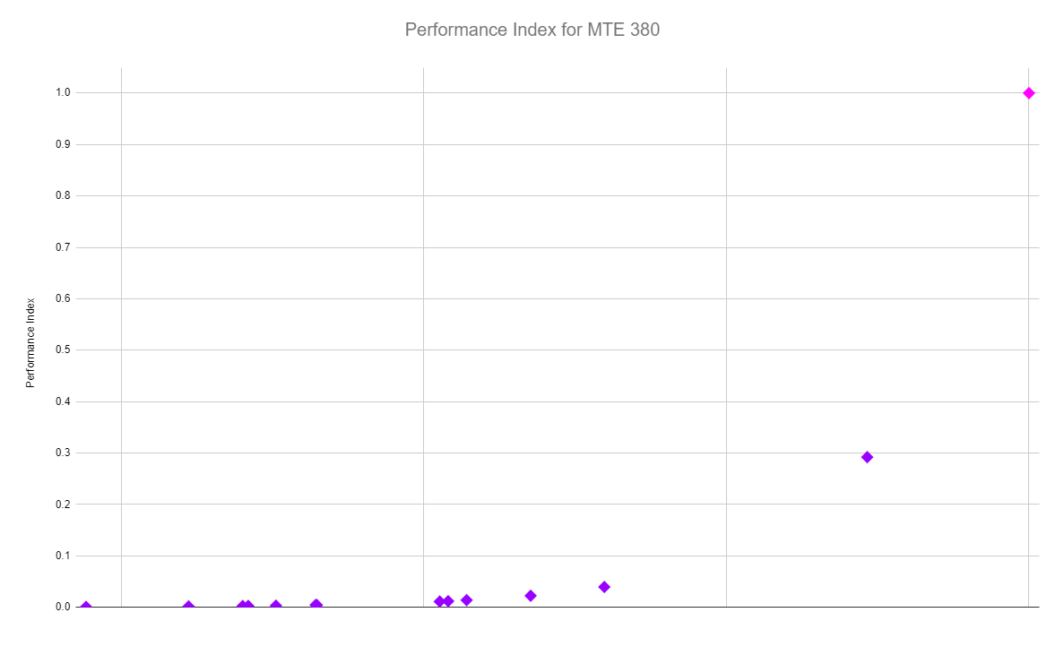
For my second term of third year (Waterloo Engineers know it as 3B), I was happy to finally have a course with a focus on building a mechatronics device, as opposed to a focus on exam based assessments. The course was MTE380, and it's purpose is to function as a 3rd year design project, a precursor to capstone. People will split off into teams of 4-5 to compete in a robotics challenge. Unlike previous iterations of the course, your base mark is no longer dependent on your competition score. But, there is still a competition aspect for bonus marks to foster a little friendly competition. Your competition score is known as the "performance index" of the robot, calculated as the following:
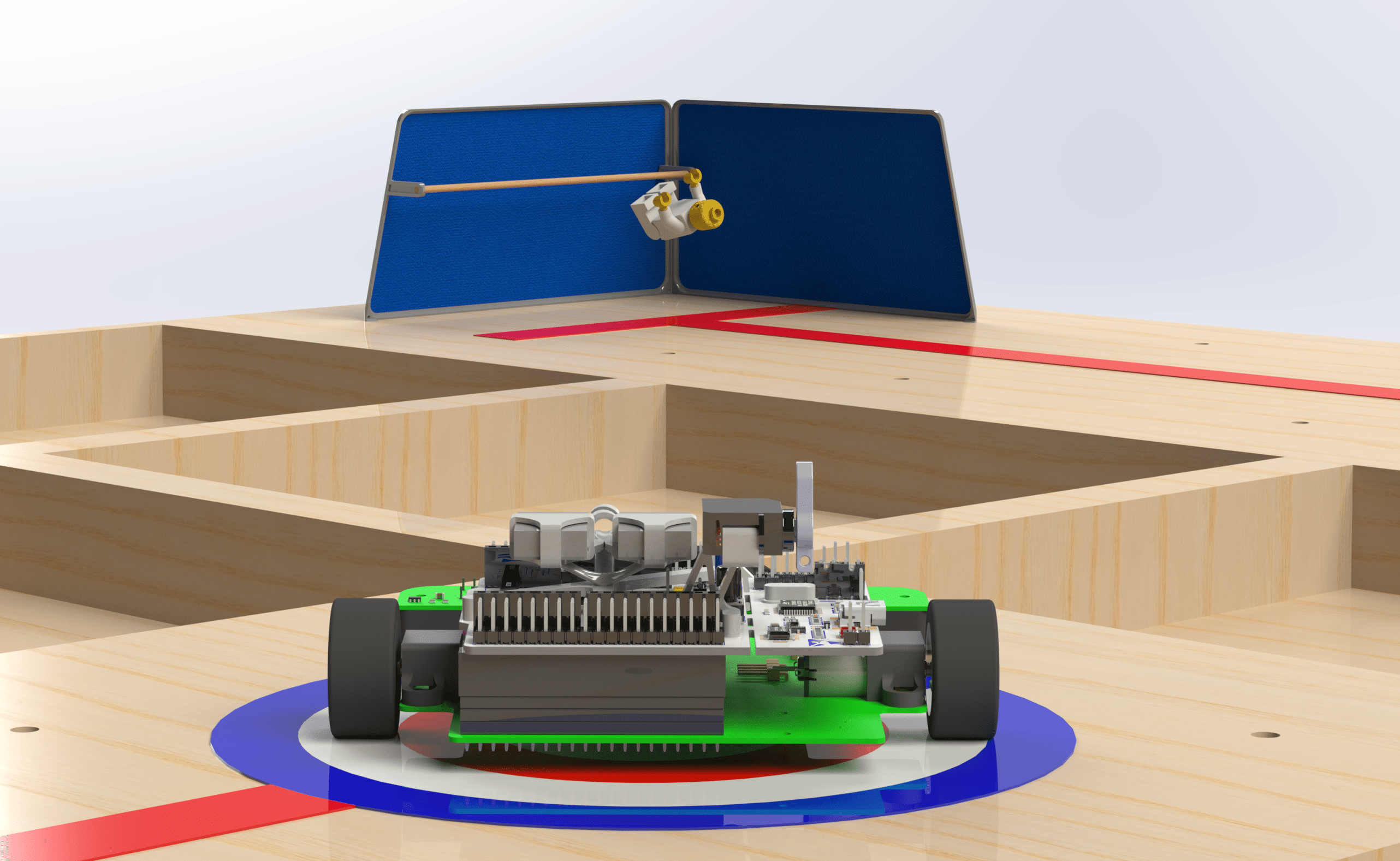
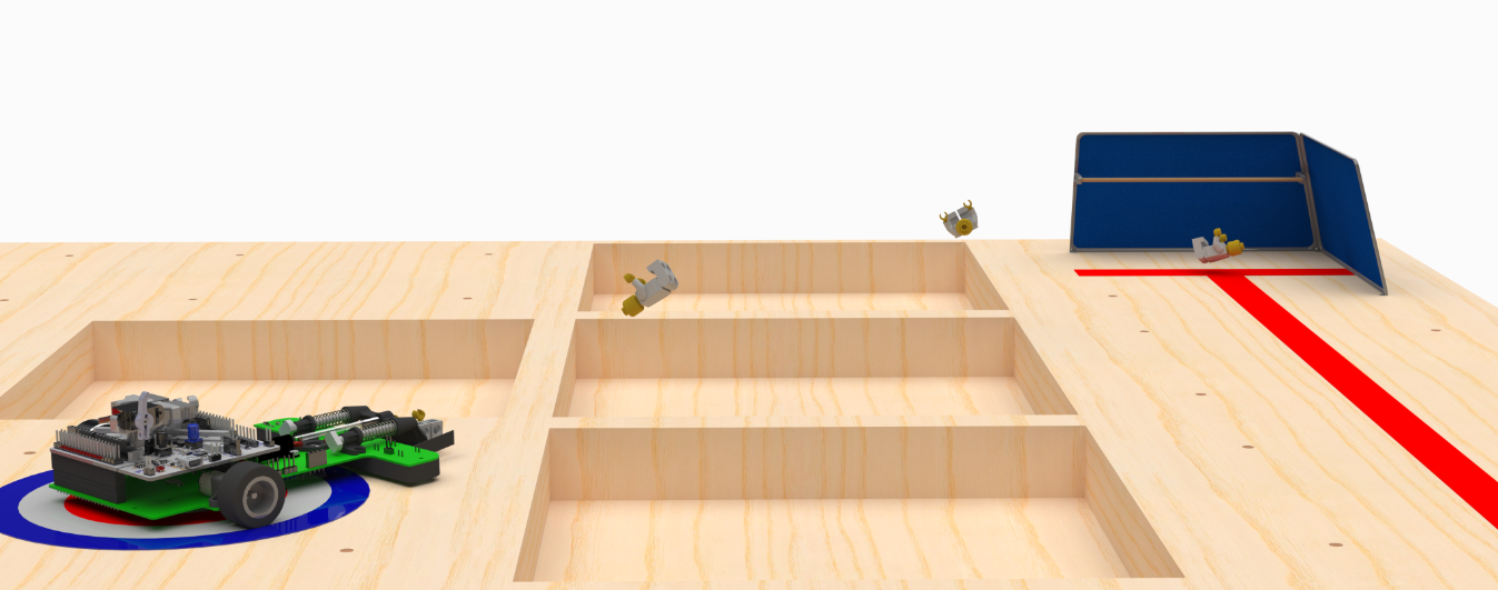
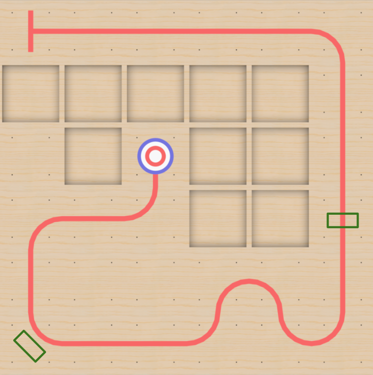
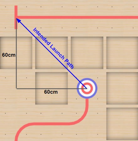
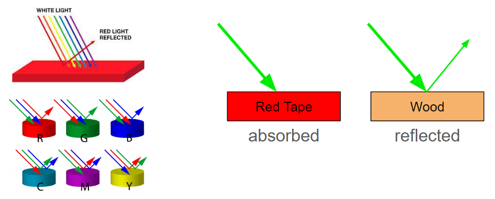
The course consists of a 6x6 grid of 30cm x 30cm squares, with a red tape path guiding the robot from the starting point (T intersection) to the target.
The rules to the competition:
- A Lego figure must be placed in the center of the target, and can be dropped off at the start of the course or in either of the boxes marked with green tape
- The time starts upon the robots program start, and ends when the Lego figure is deposited in a safe zone
- Flight and computer vision are both not allowed as per the course outline
- Making a scissor mechanism to grab the Lego from the start of the course is also not allowed (we thought we could be clever and not follow the line at all, but we must demonstrate line following prior to interacting with the Lego).
- The robot must be less than 20 x 20 x 20cm
- The robot must start and end in the same configuration (no 2 stage mechanisms, etc)
After doing some due dilligence into previous competitions, it's clear to succeed that the priority of optimization is:
1. Reduce time to complete
2. Reduce mass
The tradeoff between mass and time can be quantified, using square law:
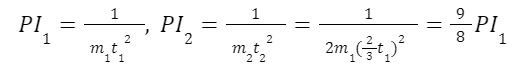
By doubling the mass and taking 2/3 the amount of time, you can increase the performance index by 12.5%.
At its core, MTE380 is a project planning course as opposed to a project course, as evidenced by only 20% of the marks being allocated for performance on game day. To acheive "perfect" marks you must:
1. Have a well built robot (/5)
2. Follow the line (/5)
3. Successfully rescue the Lego (/5)
4. Return back to the start of the course (/5)
A run is only deemed successful if all 4 of these actions are completed.
The obvious intent of the course is to build a line following robot with a four bar linkage gripper or some other intake solution, with some added mechanical and controls complexity if you want to drop it off at one of the green squares. This tried and true method was used by 20/22 teams. Dealing with a challenge that lacked some complexity compared to some of the previous course offerings (scaling a wall, underwater drones, fire fighter robots, etc), we decided to form a group of individuals keen on bending some rules, and finding some loopholes.
As to not interfere with eachothers brainstorming process, we split up to brainstorm some cool and unique solutions. Some ideas that were thrown around but didn't seem feasible/weren't allowed by the TA's include: shooting a lasso to the Lego with a winch at the start to reel the Lego back, extendind a scissor mechanism to pick up the Lego, melt the Lego down and shoot it to the start square, drive over the obstacles to pick up the Lego etc. The feasible ideas that we settled on were to make a gripper (last resort), design a geometric intake that holds the Lego and avoids the weight/time of a gripper, or to kick the Lego using compression springs/elastic bands/torsion springs, etc.
You've already seen the renders I spent so much time on, so you know which decision we went with. It was a pretty easy justification: it was the most feasible non-gripper solution allowed by the TA's, we estimated the kicker assembly to only need to weigh an extra ~40g, and save up to 10s off of our anticipated 30s run. There is likely more optimal ways to do the gripper design, but based off initial sentiment we went with kicking.
The largest issue that arises when kicking the Lego is that the entire kicking sequence has a lot of assosciated tolerances, that we expected to amount to an imprecise launch angle and distance. We decided that instead of waste time coming up with a way to mathematically calculate the stack up and create some mockups to test. I ordered a set of compression springs from amazon and started getting into some CAD (finally).
Some quick calculations were used to select which compression springs to try for kicker, using an intended launch angle of 20 degrees and distance of 85 cm. This launch angle was chosen because it allows for significant tolerance in the launch angle while still allowing the Lego to reach the start. To determine what springs to use, I estimated the weight of the Lego figure and kicker assembly based off preliminary CAD, then used assorted kinematics and force analysis to estimate the energy required to launch the Lego, before using the spring constant equation based off the torsional deflection of the spring to determine a list of springs that could work.
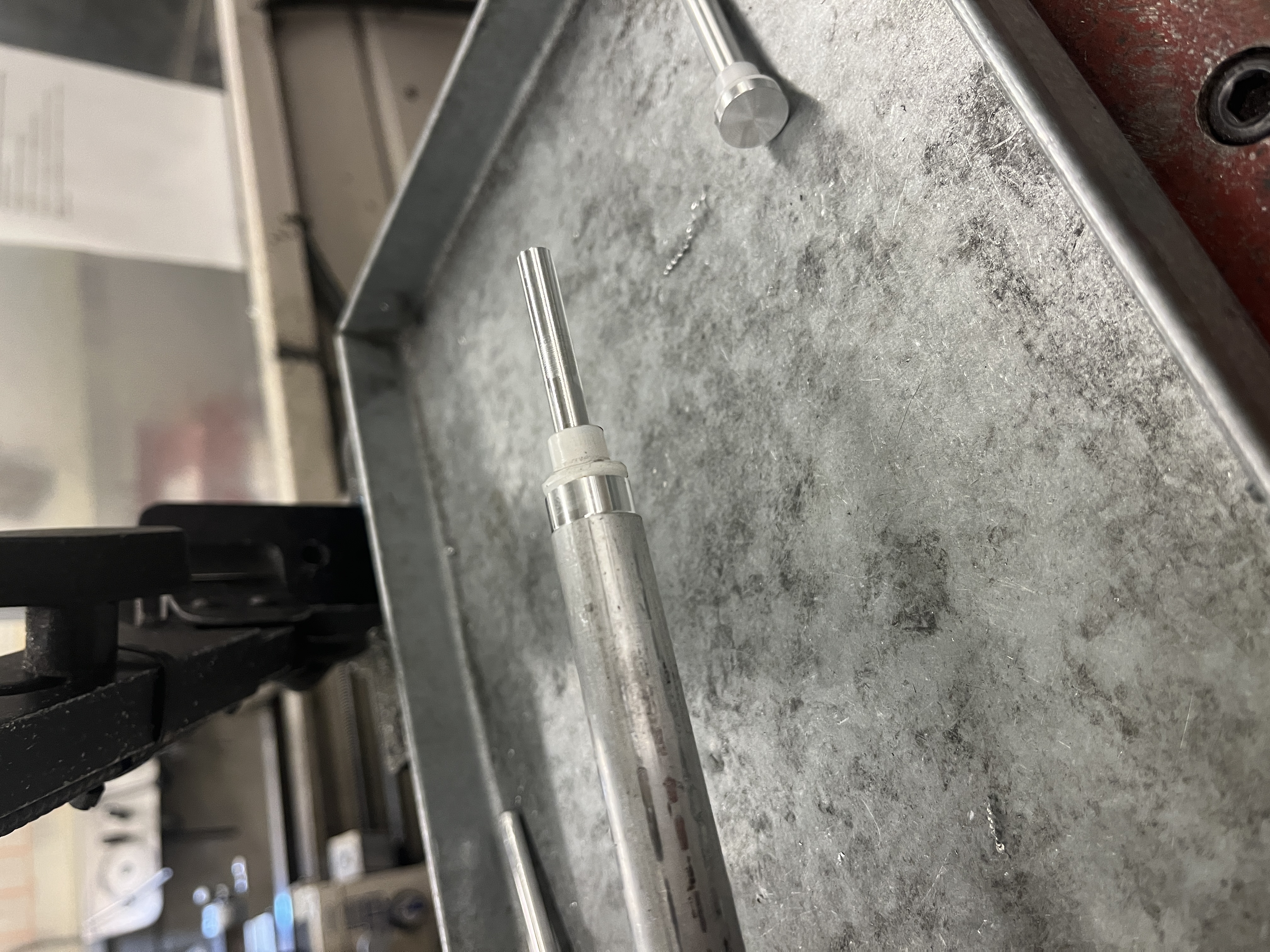
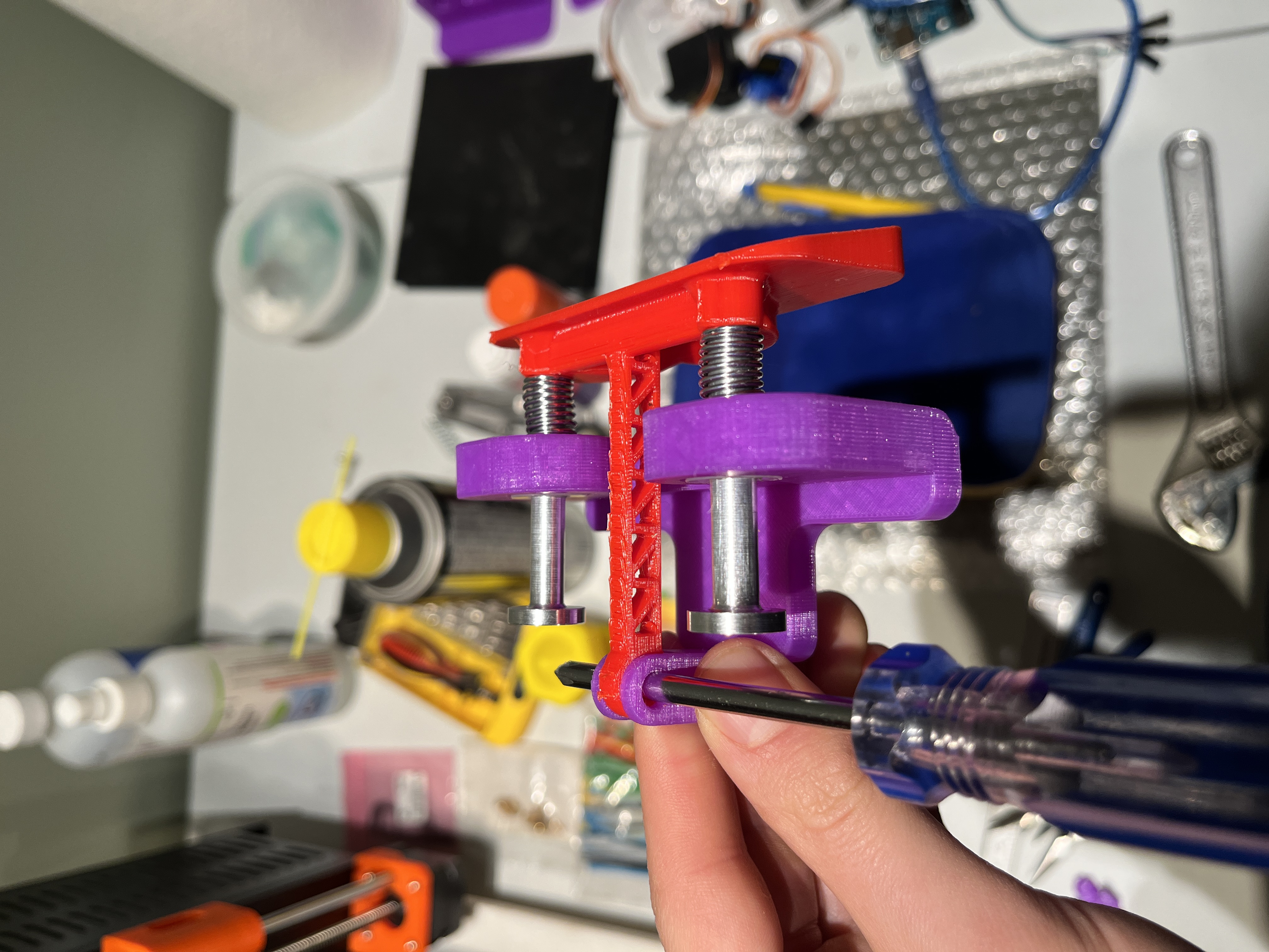
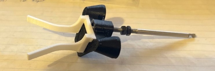
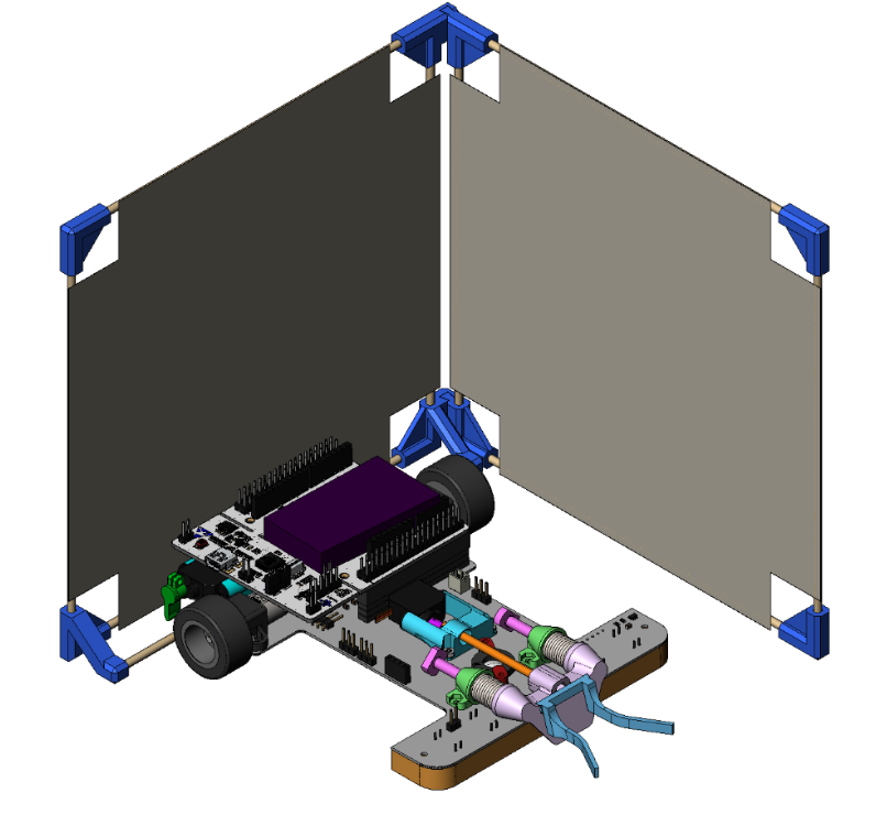
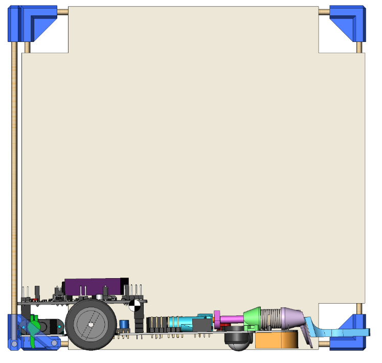
I decided to try and make the kicker part using Fusion 360's generative design tool, making use of all my student credits while I still have them. The first prototype of the kicker is relatively simple, it involved an angled impact slider, 2 plungers, 2 compression springs, and 2 nylon flange bushings. With this setup I tested a variety of kicking angles, springs, and compression distances. Since I didn't want to pay the exhorbitant McMaster Carr shipping prices, I picked up some aluminum and nylon from the machine shop and made the parts myself.
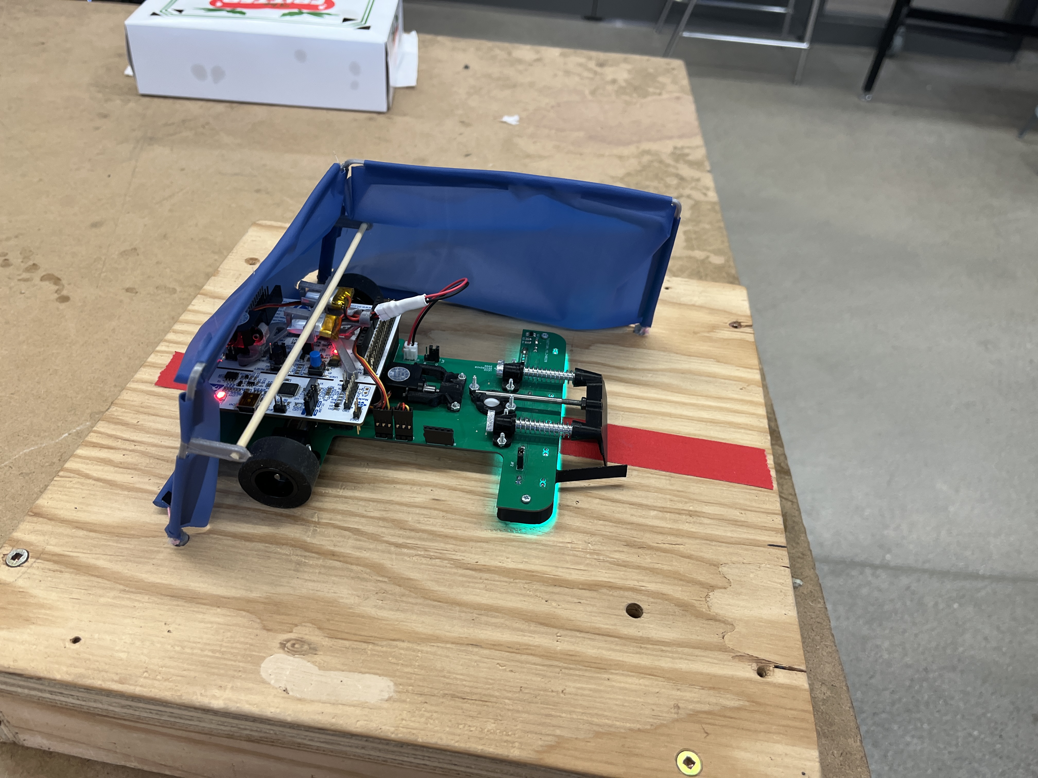
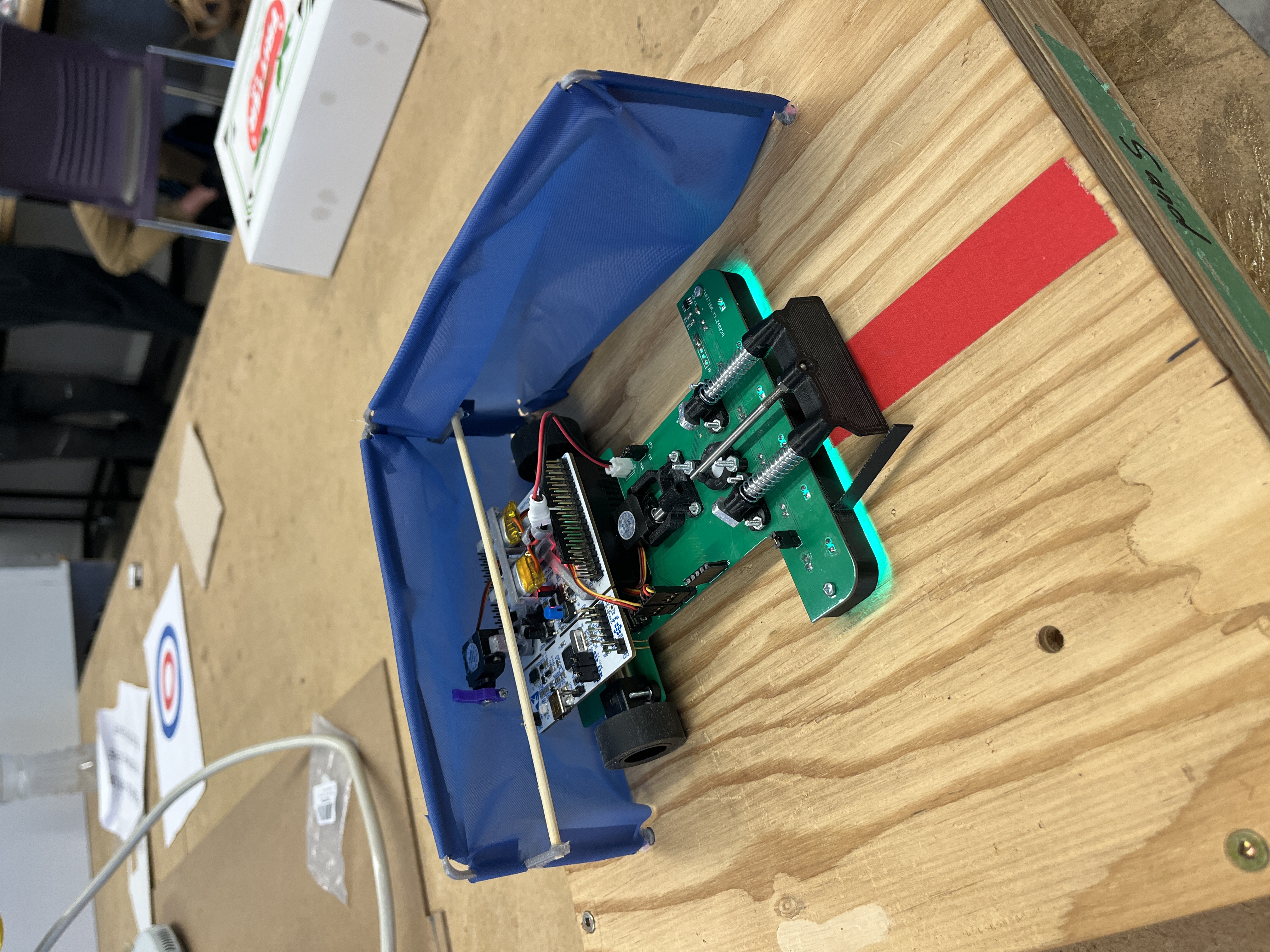
After sitting in my basement and filming ~100 kicking attempts, some with deliberate misplacement of the kicker or Lego, I concluded that as long as we could make the kicking routine mildly deterministic, kicking the Lego is completely feasible. Based on this knowledge, we went on to make our first full prototype build (with slightly too strong springs):
During the design of our Robot, we tried to mass optimize as much as possible. This resulted in the use of a lot of 3D printed parts, minimized to usually around 0.8mm thick in areas that didn't require much strength, supporting ribs, and parts that have multiple purposes, all of which posed an interesting problem. Beyond mechanical component optimization, the biggest optimizations came from battery selection and chassis design.
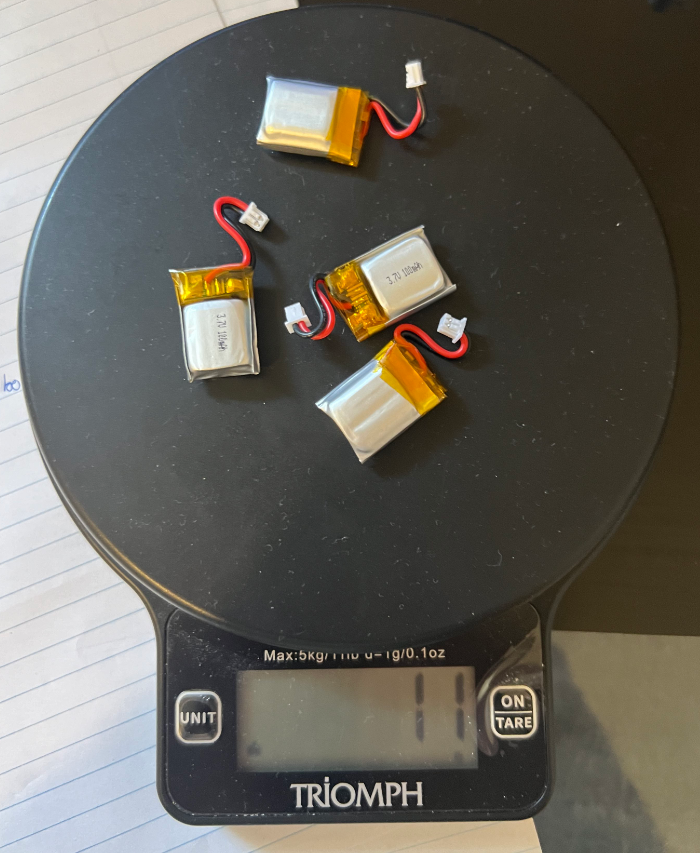
Rio (EE, FW, general aficionado) calculated the average power consumption of the Robot during our run, and we used this to spec the smallest possible batteries, about 3g each. We wired 2 of these batteries to make a 2S LiPo cell, which over volts the motors (8.4 V / 6 V), but delivers performance gains at the cost of potentially burning some motors. We are close to reaching the maximum discharge rate of these batteries (2A), but can get 2-3 runs out of them before the voltage drop noticable affects performance. The motors we ended up using are 30:1 Polulu micrometal gear motors, calculated using required drive speed and torque for accelerating in the straights. The desired finish time to get from the start line to the target was chosen to be 7s. On competition day, the line following time was about 7.5 seconds. Which is very close to the calculated value. We also tested 1:10 early in development.
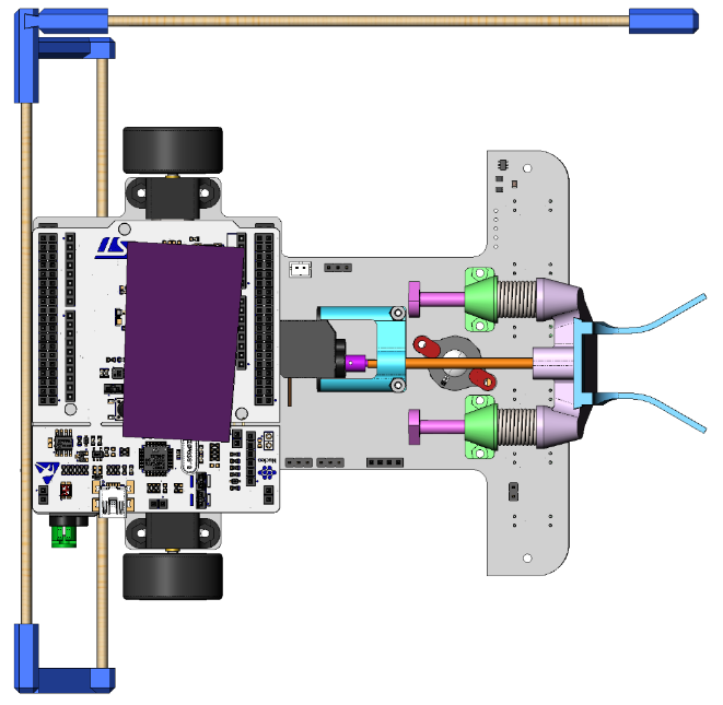
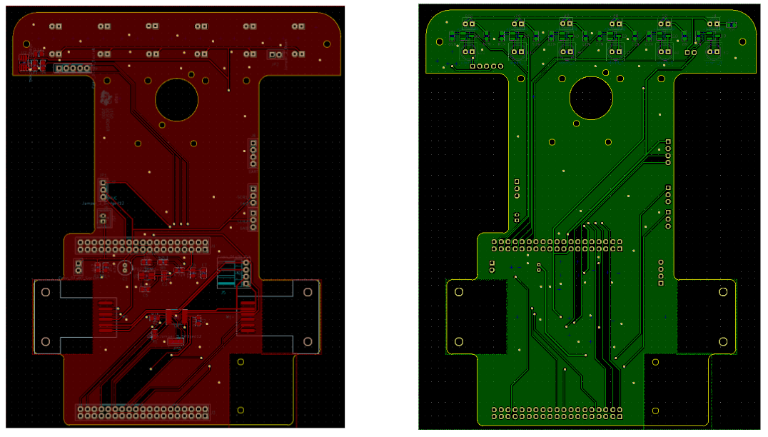
To make the robot as light as possible, we elected to use 1mm thick PCBA as the chassis for our robot. This accomplishes a couple things:
1. FR4 composite is quite strong relative to its weight when compared to materials like acrylic.
2. We can route all the traces we need, avoiding ugly wires that can be tricky to debug.
3. We had already extensively tested all electrical sub systems, and were confident in their use for the final robot.
Ideally, we could have soldered the components for the nucleo directly onto the board, which would be a huge cost saving. However, one thing to keep in mind is where the center of gravity is of the assembly relative to the wheels. With all the kicker and electrical components mostly pushed towards the front of the robot, and extremely light batteries, without the nucleo the center of gravity would shift forward. This is not ideal, as to deliver maximum torque and have the highest traction, the center of gravity should be in line with the center axis of the wheels. Doing a quick CG study keeping the nucleo on the back should drastically enhance traction performance. After careful routing and review, the PCBs were ordered at the end of February, just before midterm exams.
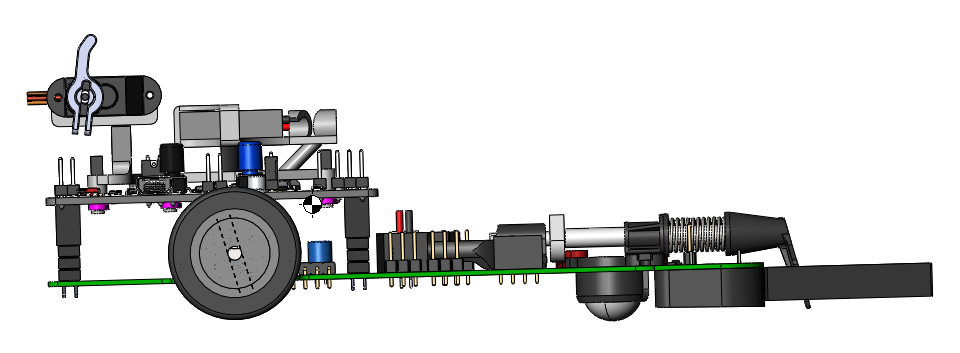
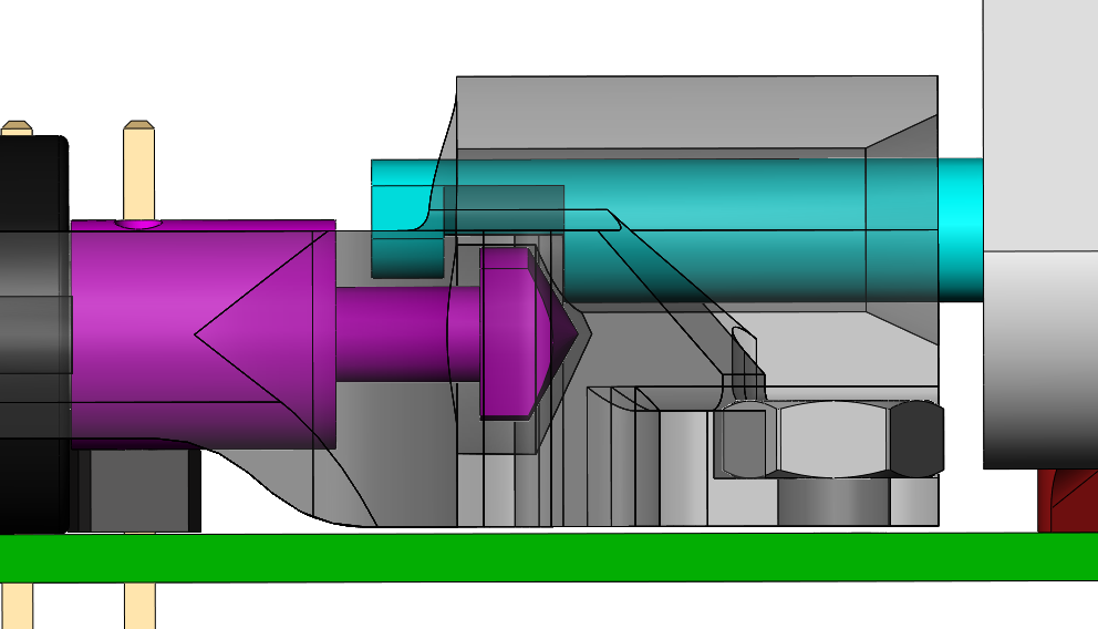
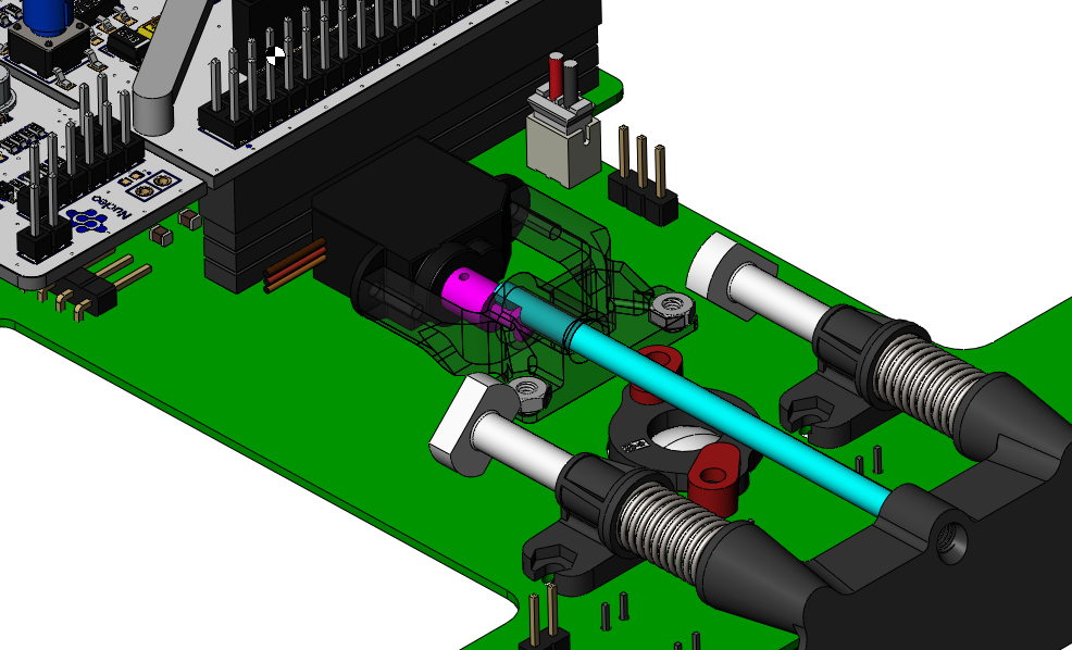
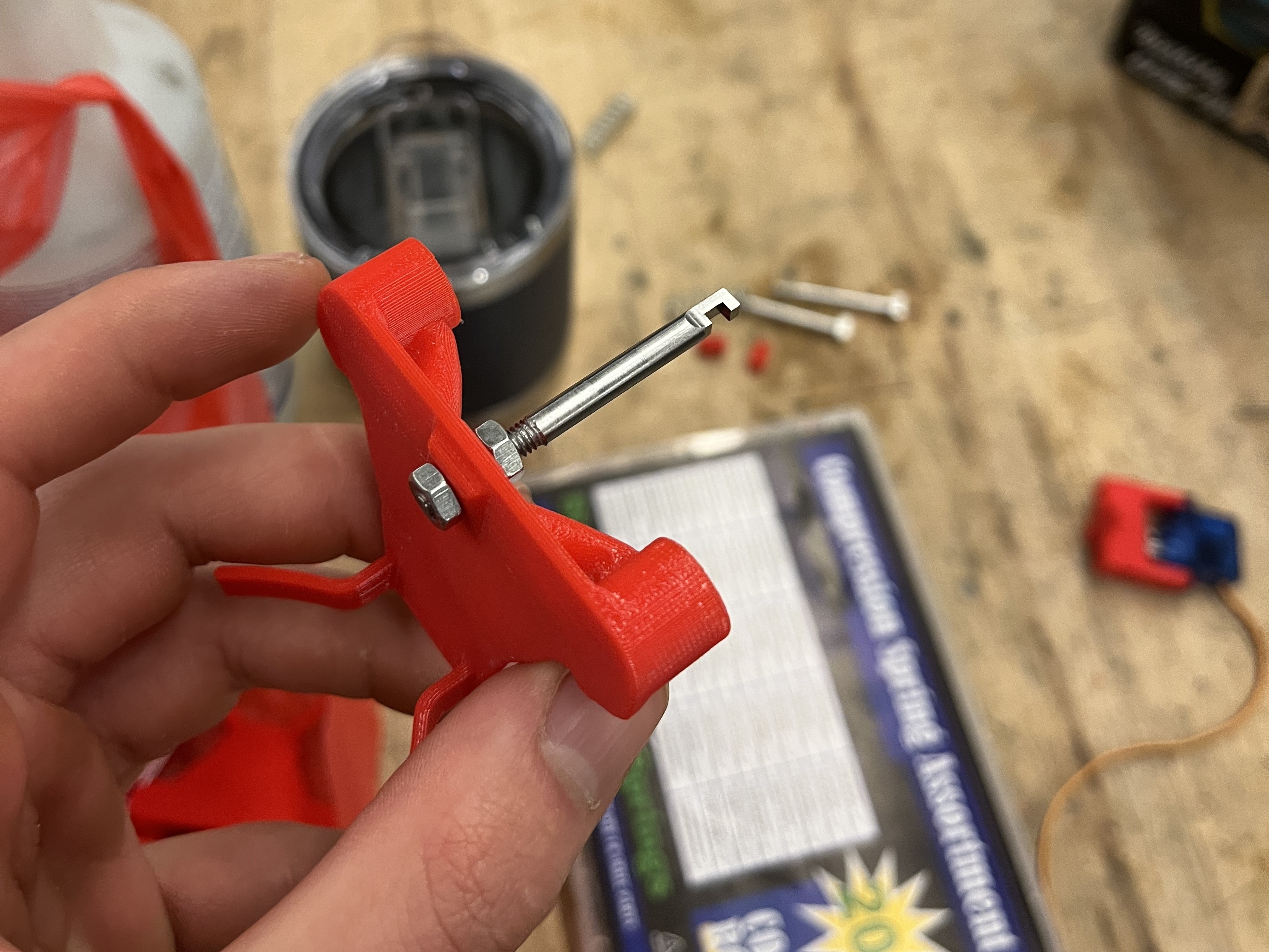
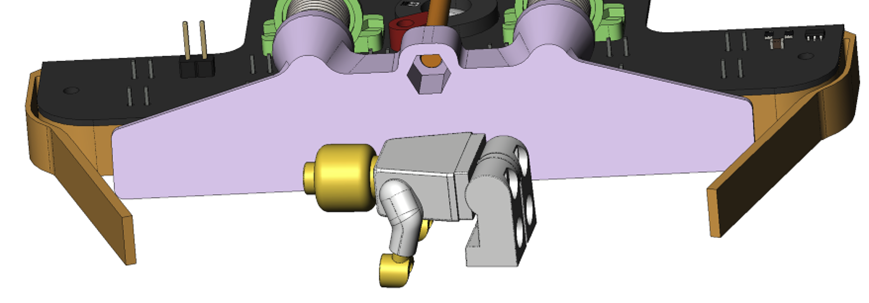
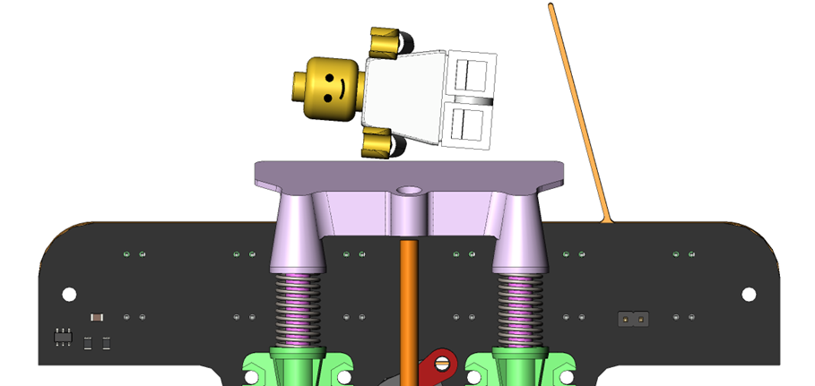
The PCBA arrived and worked! We needed to add a small jumper to ensure the motor driver was in the correct operation mode. With a working drive platform, the rest of the components needed to be fabricated. This includes a lot of 3D printed pieces, and some machined. As mentioned before, the 3D printed parts are weight optimized without sacrificing function. Components made out of metal needed to be for proper longevity of the robot. These parts are the 2 spring plungers, and the interlocking release mechanism components. The kicker is released using a 2g servo motor, the motor rotates the pink part out of the way of the teal part, requiring near 0 force to release the kicker. The plungers were made of aluminum, while the kicker parts were made with tool steel.
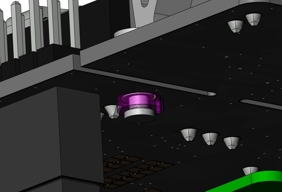
The battery holder is held to the nucleo using super small snap on shaft collars, which worked way better than I thought they would. Using needle nose pliers, it was a sub 2 minute operation to swap battery holders which was much better than previous iterations, which use fastener or press fit solutions. The rest of the mechanical components: front shroud, trigger servo block, guide bushings, and motor holders are all secured using M2 screws and nuts. We could go down to M1.6, but ordering those from McMaster would eat too much into our budget. Since we need to swap batteries every 2-3 runs, I designed a holder geometry reminiscent of a cable organizer. Batteries can be swapped in less than 30 seconds. It was starting to feel like a pit stop between runs when we would swap batteries and clean the tires for better traction.
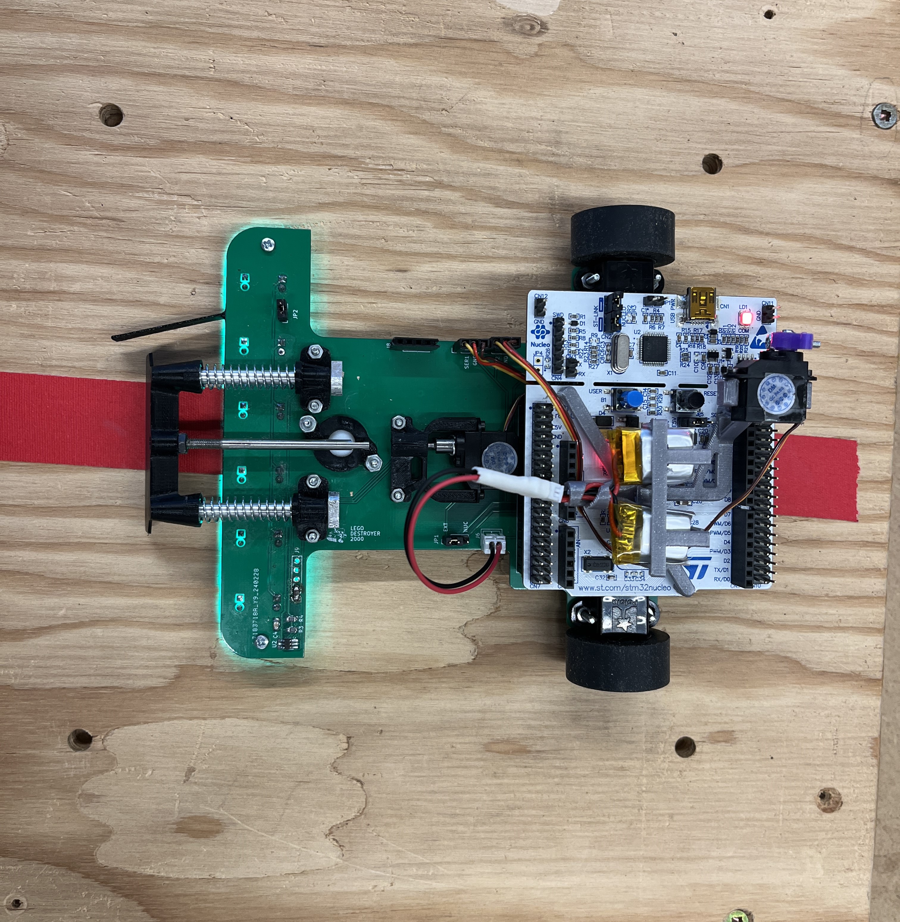
On competition day, our robot weighed 178.5g, the lightest in our class by 70 grams and half of the average weight.
I've already discussed the design of the actual kicker, but another critical challenge of kicking the Lego is ensuring proper alignment, both relative to the robot and to the target. This challenge requires open loop control, there are no sensors on our robot that indiciate the position of the Lego, meaning that we can detect target and make assumptions as to where the Lego is within the target. As a note, for the competition we can place the Lego wherever we want, as long as it is within the center white circle of the target.
Early prototyping was done based off the assumption that it made more sense to have the intake on the kicker. Intuitively, this allows us to ensure alignment of the Lego during the entire kicking motion. In reality, it is very difficult to quicly iterate a geometry that can intake the Lego accounting for minor positional errors during alignment, deterministic kicking, and doesn't lose the Lego during aiming (which has some jitters due to the PID controller).
After a lot of wasted effort trying to get the kicker mounted intake to work, we went in the opposite direction. Widening the kicker to almost the width of the robot, and using compliant flexures on the shroud as an intake guide. While this geometry was excellent for intake and aiming, the kicking had too much deviation to be feasible. It also added a couple extra grams.
More testing showed us that the size of the kicker paddle and the intake could be shrunk to reduce the weight of the kicking mechanism and the overall robot. It was also noticed that the intake's flexural arms made taking the Lego figure less reliable due to random impulses. Later testing showed that aiming could be done in one smooth motion. This means that the left side guide arm was not used during any part of the run and could be removed to save some more weight. The final intake design uses a thin (0.8mm thick) plastic arm, perfectly positioned and sized to interact with the Lego figure. This arm is a part of the already existing shroud part. The negative angle of the intake ensures the Lego figure is correctly positioned for launching after the aiming sequence is completed.
Another critical mechanical component to our robot was the catcher. After discussion with the teaching team, we were allowed to leave a net or barrier at the start square to catch the Lego (since the course walls are considered "an infinite boundary") if we met the following criteria
1. The catcher starts mechanically somewhat attached at the beginning and end of our run. Somewhat meaning that if the Robot were to drive it would drag the catcher with it.
2. The catcher must also remain within the 20cm boundary cube.
3. The Lego must be touching the wood tile for the run to be successful.
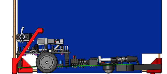
We are not allow to glue or tape the catcher down to the start square, but the robot is able to. This led us to our first catcher iteration, made of 3D printed corner attachments, balsa wood BBQ skewers, and table cloth. Along the bottom of the catcher is a crossbar, which is latched and unlatched using a second servo motor (dubbed as "catch-attach") placed at the back of the robot. At the start of the run when the hook is down, the robot drags the catcher, qualifying as "somewhat attached".
Through empirical testing, it was determined that with the crossbar below the robot, the Lego would get pinned between the robot and the bar, preventing the robot from latching at the end of the run. Moving the bar above the robot allows it to be offset by at least one Lego figure length to ensure that even in a worst-case scenario, the robot can still latch effectively. Moving the crossbar above the robot is slightly risky on the off chance that the Lego hits the crossbar and is bounced out of the start square; however, this became a non-issue for a point to be discussed in the game day section. The more imporant issue at hand is the movement of the catcher after stopping the Lego.
Upon closer inspection, each tile on the course contains four holes for alignment pegs, conveniently arranged in an 18 cm square. This was leveraged by adding pegs to the catcher to prevent it from sliding upon impact with the Lego figure, making the entire end sequence more deterministic. With further testing and spring refinement, it was decided that the top of the catcher could be safely lowered from 180mm to 95mm. Although the Lego could go over the net, it was unlikely, and the weight saving was worth it.
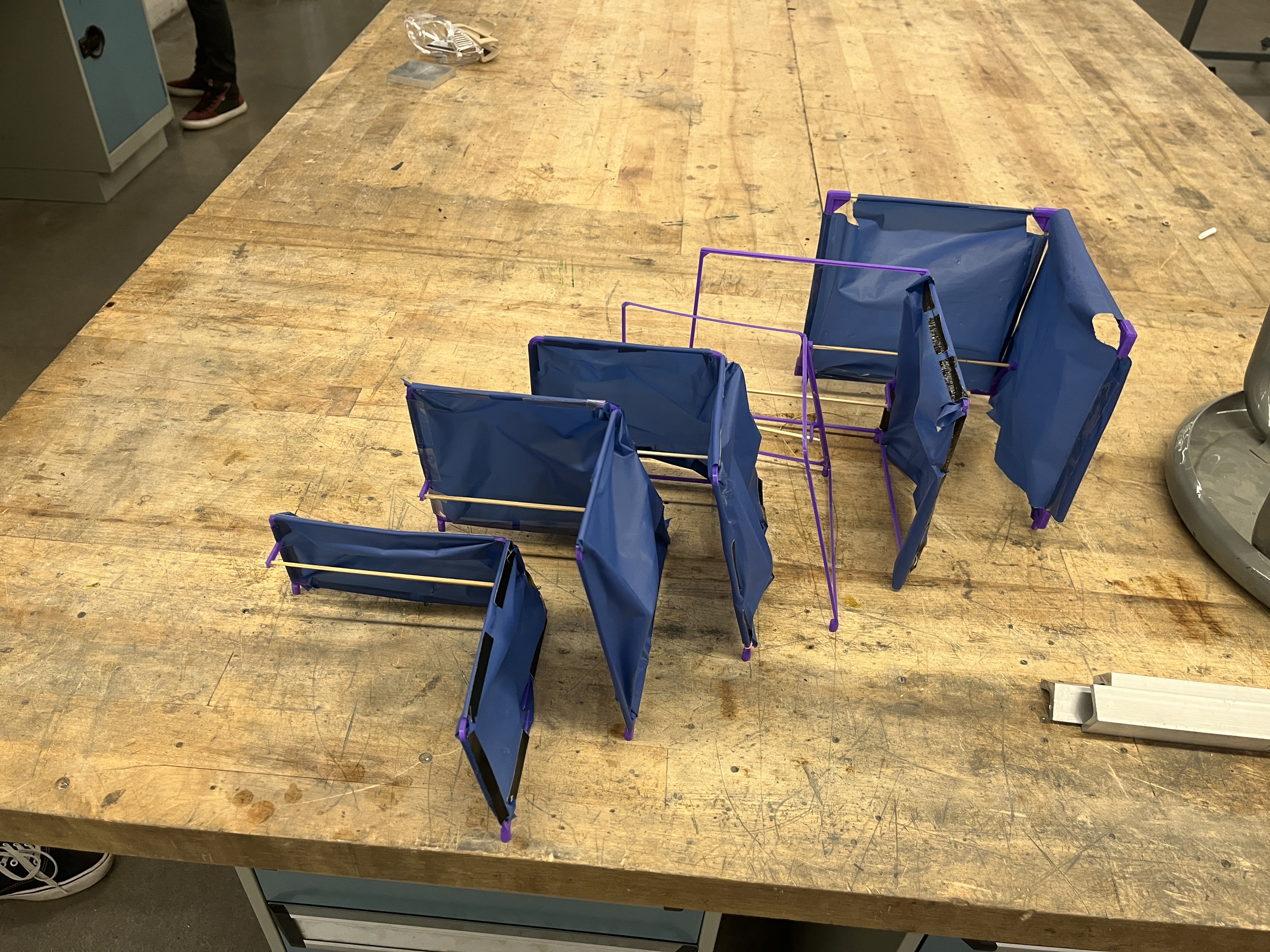
The wooden dowels were convenient for quick prototyping and not wasting a bunch of 3D printed plastic, however they were still pretty heavy. At this point, the catcher still weighed over 25g, a large enough percentage of our robot that it was considered an issue. The catcher was switched to a fully 3D printed frame, made with a swept L-beam profile, 1.2mm thick at all points. This catcher was nowhere near as sturdy as it's wooden counterpart, which ended up working in our favor. Because we can use the holes in the course for our catcher, we don't have to worry about it going anywhere. We can then optimize it for what it was intended to due, catch the Lego. The L beam frame is strong enough to support it's own weigh, but deflects upon impact with the Lego, the deflection dampens the impact of the Lego, preventing it from bouncing straight off the catcher and out of the start square. This is also why the net is purposefully quite loose on the catcher. At the start of the runs the net is flared outwards, so it can slow down the Lego for a further distance. The net cannot be too loose, or else it would catch and hold the Lego, as opposed to gently releasing it to the start square.
The final catcher combined all of these learnings, and had one extra trick up its sleeve. With 2 weeks before the competition, we decided it was worth the engineering time to start prototyping angle catchers of various decline (10, 15, 20, 30 degrees). The angle deflects the Lego downwards towards the start square, preventing it from getting caught in the tarp and having the Lego settle against the start square earlier, two things that were helpful for having a successful run and optimizing run time. One final change was to remove the bottom beam of the catcher; the pegs already added the rigidity along that section, and it aleviated any risk of having the Lego get caught in the catcher. The beam was replaced with some string so that the net still had structure. The final catcher weighed 13g.
.JPG)
Rio and Ethan worked on the electrial side of things, I'll link there in depth writeups later, and skim over the electronics here for context.
The electrical system consists of the following components: 5V Buck converter, Battery connector and voltage sensing, I2C compass, which ended up being unused, LED + photodiode sensor array, H-bridge DC motor driver, Brushed DC motors, Infrared optical encoders, Servos, Bluetooth UART module for debugging and tuning, Nucleo F401RE.
All motors and servos run on the unregulated battery voltage from 7.4-8.4 V. The LED array and motor encoder run on 5V from the buck regulator. The rest of the circuit runs on a 3.3V rail created by the Nucleo’s on-board regulator. Rather than relying on the internal 5V regulator on the Nucleo, we chose to add an external buck regulator to provide a higher current to the LED array.
The power source is provided by two packs of Li-Po batteries in series. With 100mAh each, they provide enough charges to finish the course just a few times. In exchange, we get massive weight savings. The pack weight is ~5g in total. For reference, the 350mAh battery we used during the prototype was ~25g in mass.
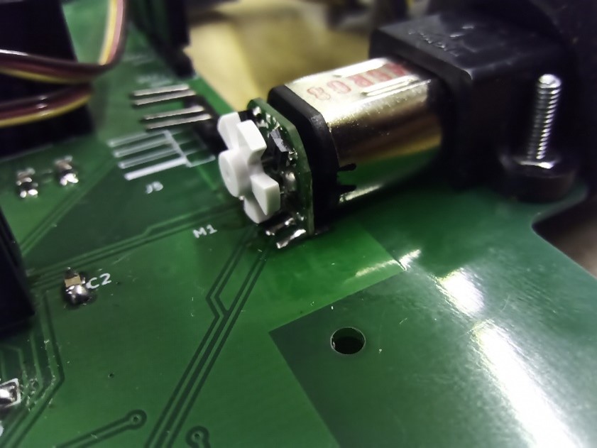
Two 30:1 Pololu motors are used to drive the wheels. These motors are rated at 6V, which is overvolted to 8V for this project, considering the short-life nature of the project and part availability. These motors provide decent speed and fast response, allowing the robot to follow the line speedily. A Pololu optical encoder is added to each motor, providing motor position feedback and connection to the PCB.
The sensor array consists of 6 LED – photodiode pairs, with built-in IR blocking filters. With a green LED, the pair can effectively sense the difference between the red tape and the wood tiles.
The overall architecture is a 1kHz superloop. Each module gets to run once every 1 ms at equal priorities based on timer interrupts. STM32 HAL is used to control low-level hardware. The sensor readings are combined using a (signed) weighted average, such that the result reads 0 when the line is in the center of the array. Each sensor is calibrated at two points—on top of the wood floor and on top of the red tape—and the readings are normalized. The final value is latched using the minimum value read across sensors. This way, the robot will remember the line’s last direction when it gets lost.
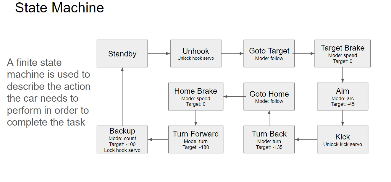
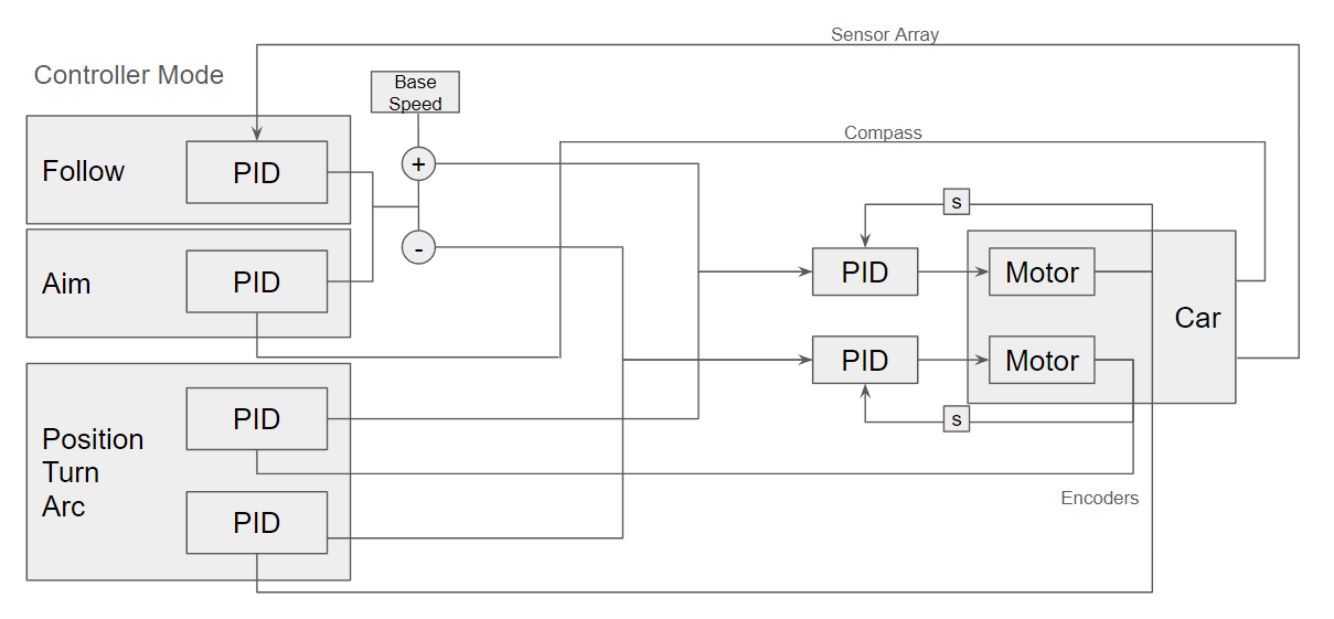
The robot uses a cascaded control. Each motor has a speed controller to maintain speed across battery voltage variation. Depending on the control mode, the reference input for these controllers is generated by another controller. For line following mode, a PID controller is used. For the arc, turn, and move modes, speed is controlled based on each motor's encoder count. Chaining controllers like this allows the robot to have consistent and easy-to-configure behaviours.
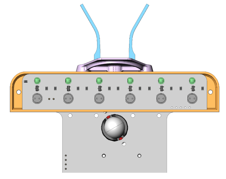
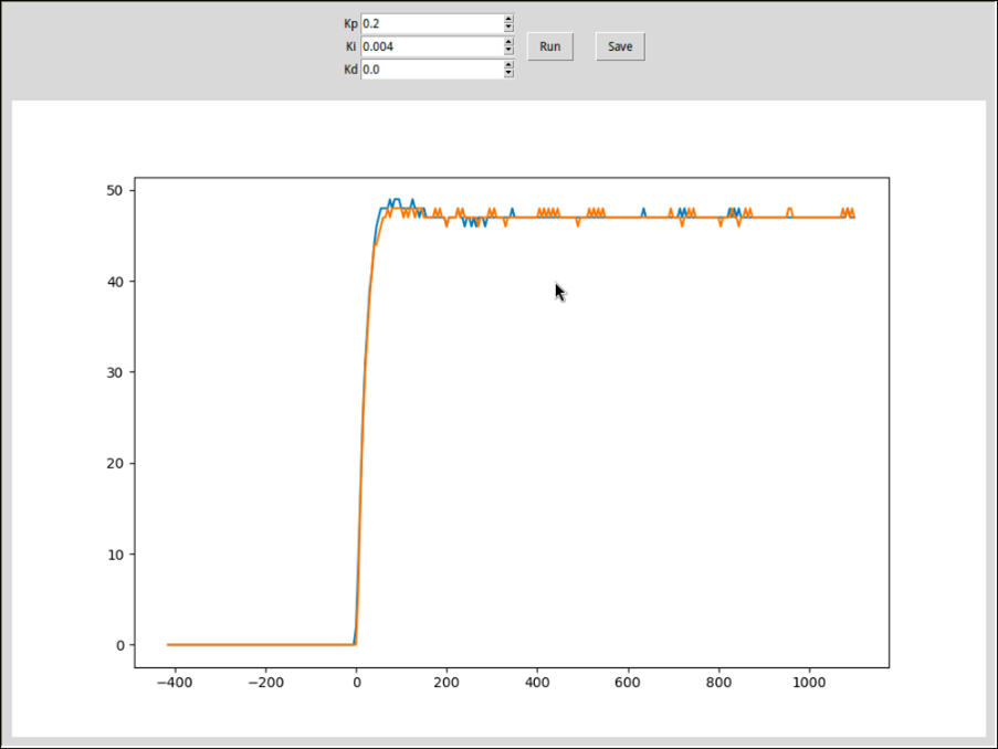
The PID Tuner (“the tuner”), serves as a graphical interface to visualize the step response of the left vs right motor, along with inputs to adjust all settings. The tuner sets the robot speed and PID values, then runs the motor for a set time and records the response. This helped in configuring motor PID for near-instantaneous response.
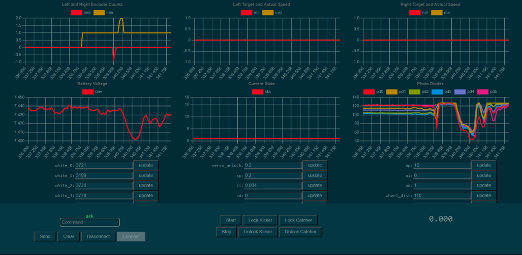
The Graphical Control Panel (“the interface”) provides additional graphical data for the entire robot, rather than solely the motors. The main usage of the interface is to provide graphs to show live streamed data from the robot and to provide an easy method of controlling the robot. The data from the graphs covers encoder counts (left vs right), motor speed (actual vs target for both left and right), battery voltage, state, and photodiode readings. The control set on the bottom includes a command input, a quick access panel, and a timer for the design check specification.
Our last testing before game day was at around noon the day before. After successfully completing five consecutive runs, it was decided not to do any further tuning, keeping all components fresh for game day. We didn’t properly anticipate the amount of wear the track would go through in the next 24 hours. The track likely saw use for those 24 hours consecutively, with some groups allegedly staying overnight to test. On game day we were confident, due to some fine print in the course outline. The course outline states that when calculating performance index, an attempt is defined as a run lasting longer than 10 seconds. This fine print turned into an instant cheat code for our robot. During our testing, the Lego typically landed in the start square at around the 8.4s mark. However, not all runs were perfect; sometimes the Lego would bounce out of the start square, sometimes the aiming sequence was slightly off and it missed the catcher, etc.
We showed up on game day with a final robot weighing 178.5 grams. Our first run was completed successfully, completing the full S&R course in 8.34 seconds. The next four runs were unsuccessful; the robot was unable to aim and shoot the Lego figure properly. This was likely due to a combination of all the dust and dirt on the track and some tiles that were slightly mismatched, creating an inconsistent line.
After some wheel and track cleaning, the robot completed 3 successful attempts (with the previous failed runs occurring before 10 seconds had elapsed, nullifying them). This rendered a “perfect” reliability score. Our second run resulted in our best time of 8.04 seconds, making our final performance index:
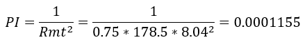
Which was the highest, giving us 1st place. We were both the lightest and fastest group, and the only group with a perfect reliability score. Our performance index was ~3x better than the next highest in our class, and ~20x higher than 3rd place.
To many, this project was just something that they needed to pass. To us, this project was much more than a barrier to getting a piece of paper; it was an opportunity to experience the engineering design process, encapsulating the challenges, setbacks, breakthroughs, and, ultimately, the triumphs.
Our game day attempts:
Variable Mass & Flow SKU
Variable Mass & Flow SKU
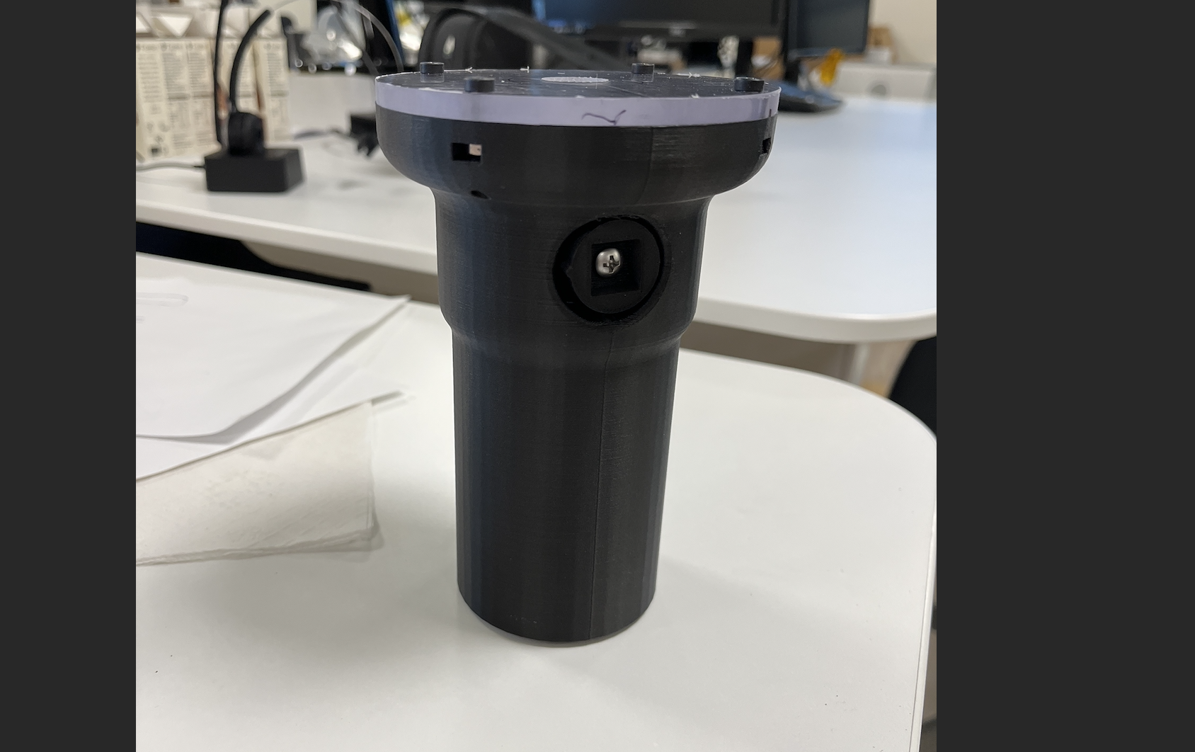
An object with variable mass and porosity, used to replicate any grocery item for robot characterization.
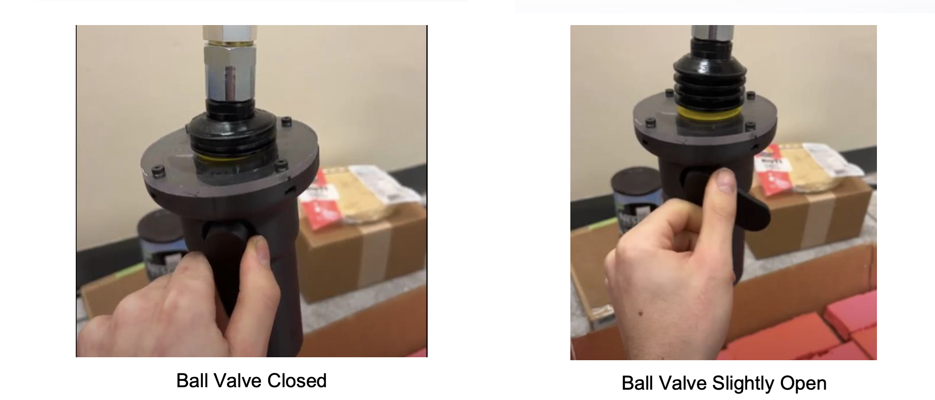
The purpose of this project is to create an object that has a variable mass and “porosity”, that can be used to imitate a wide range of grocery objects. Custom aluminum weights were made from aluminum stock on a lathe, each weighing at 250 ± 0.05 g. The object simulated vacuum leakage via an adjustable ball valve, which can be altered from fully closed to fully open depending on the desired leakage flow. FEAs were run on each FDM and MJF 3D printed part to reduce the base weight of the item as much as possible (up to 50 %) while avoiding leakage in the vacuum line. MJF parts were used along the vacuum flow line to eliminate any air leakage, and an O-ring was used to seal the pickable acrylic surface to the MJF part and ball valve.
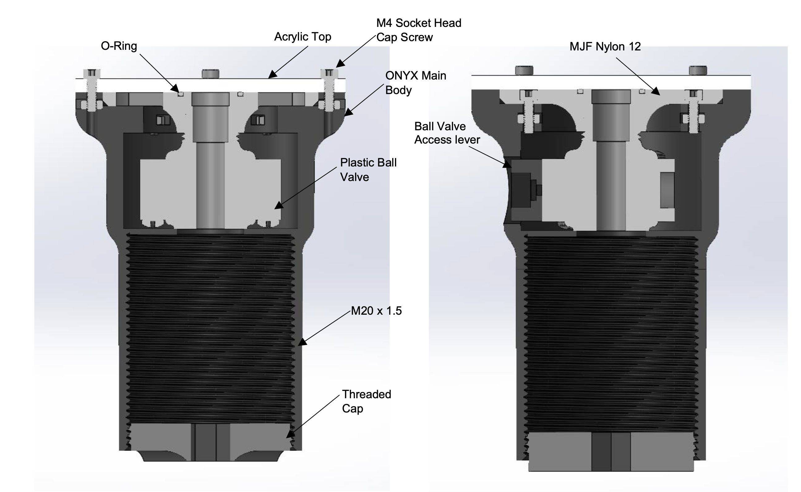
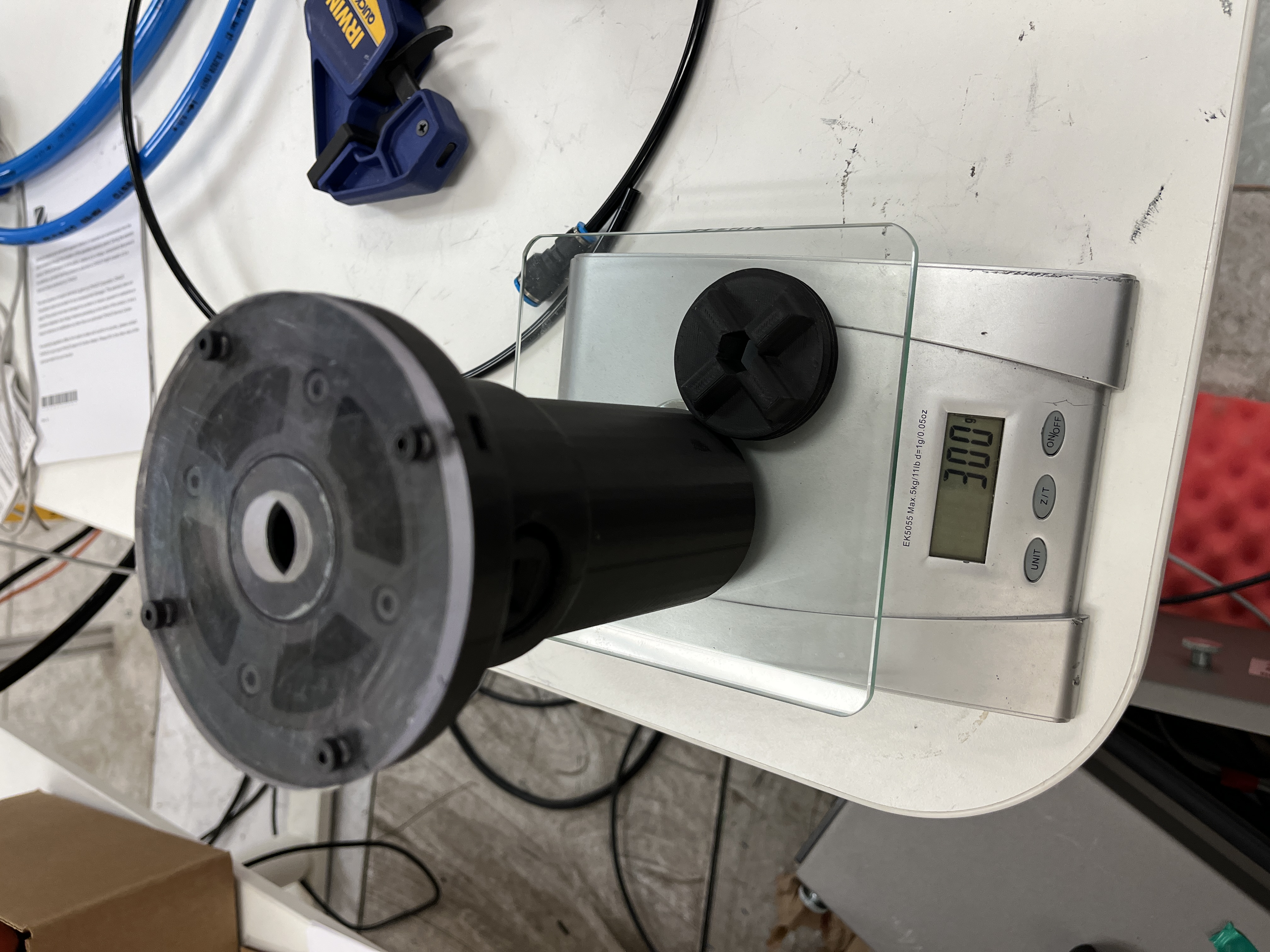
My largest design challenge with this project was coming up with a way to retain the masses securely inside the object, while keeping the center of mass in line with the picking axis. Designs that I considered where: threaded tube and cap to secure any size weight, twist-lock mechanism in the cap and body, tight friction fit masses, retractable spring plungers to lock masses into place. The threaded option was selected due to its simplicity and scalability, the twist lock and spring plunger mechanisms would only allow the pre-made 250 g weights to be used, without the ability to scale to using smaller or larger denominations of weight in the future. Friction fit masses were not used due to the difficulty of removing the masses after testing, as well as the risk that during robot acceleration a mass flies out.
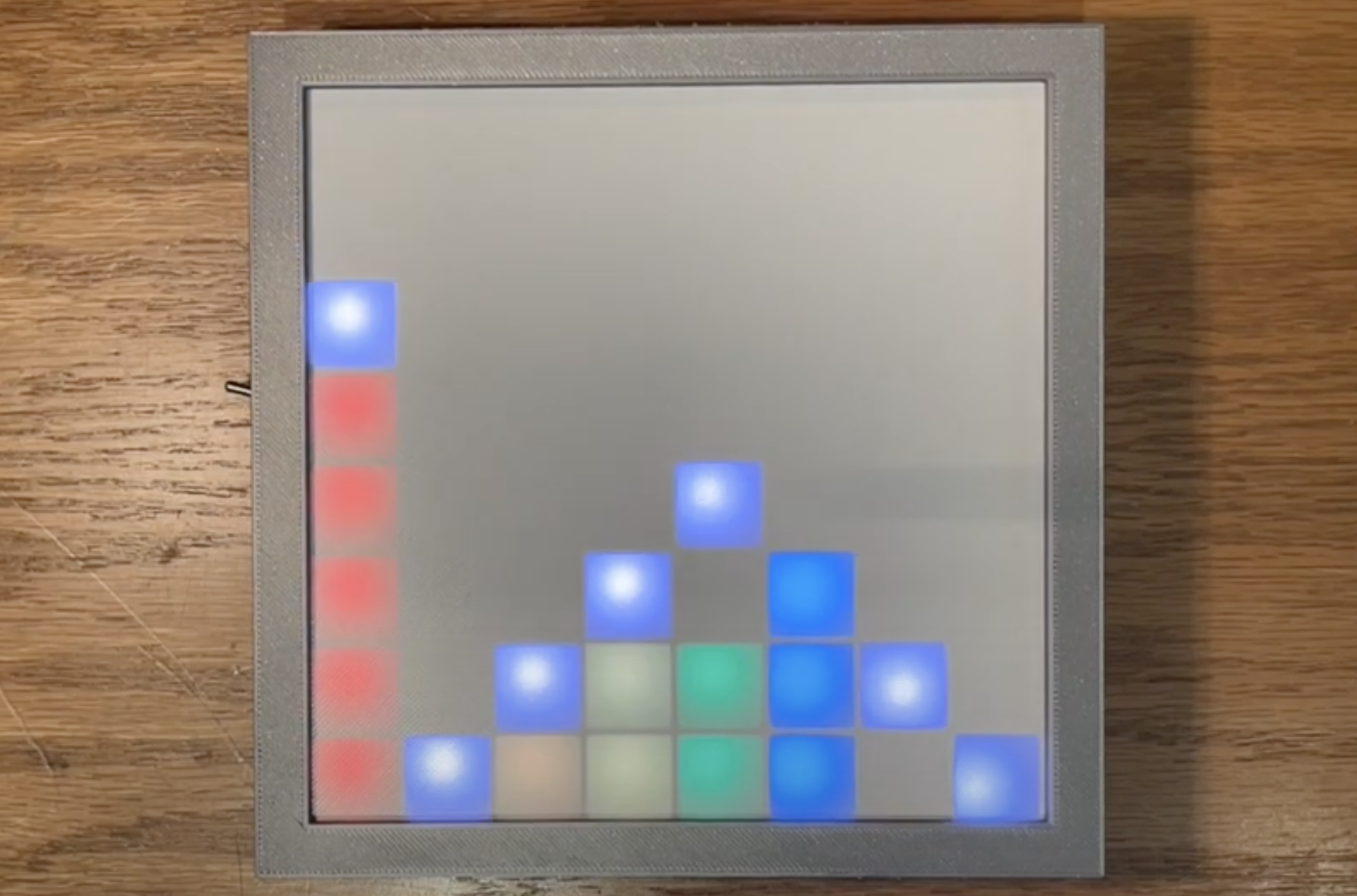
LED Equalizer
LED Equalizer
Another LED Equalizer, this time, web enabled :).
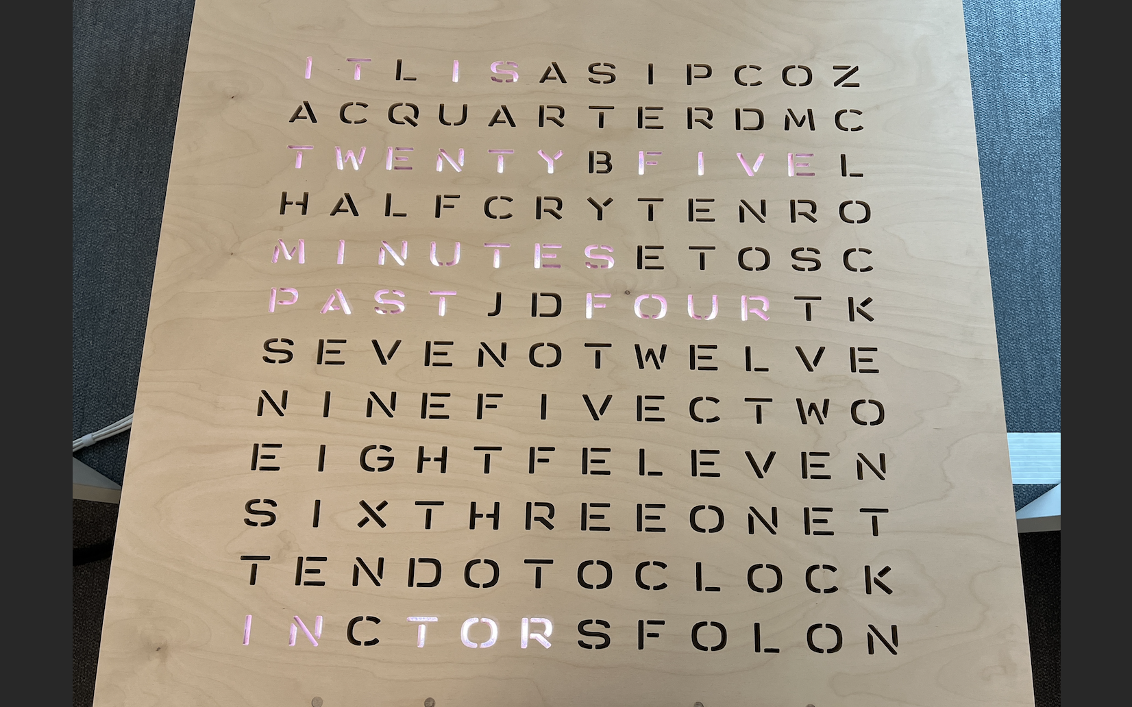
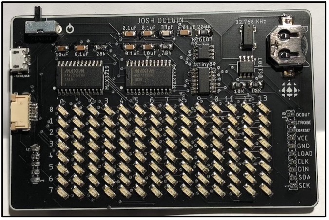
OMERS Word Clock
OMERS Word Clock
Affordable, Open Source, art display for OMERS Venture Capital.
The word clock is a unique mechanical engineering project that combines innovative design, electronics, and software to create a stylish and functional time-telling device. The project features an LED matrix display that spells out the time in words, making it both an aesthetically pleasing decor piece and a practical clock. The design integrates various features, such as an RTC (Real-Time Clock), LED animations, a web server for configuration, power management, and an IP address display.
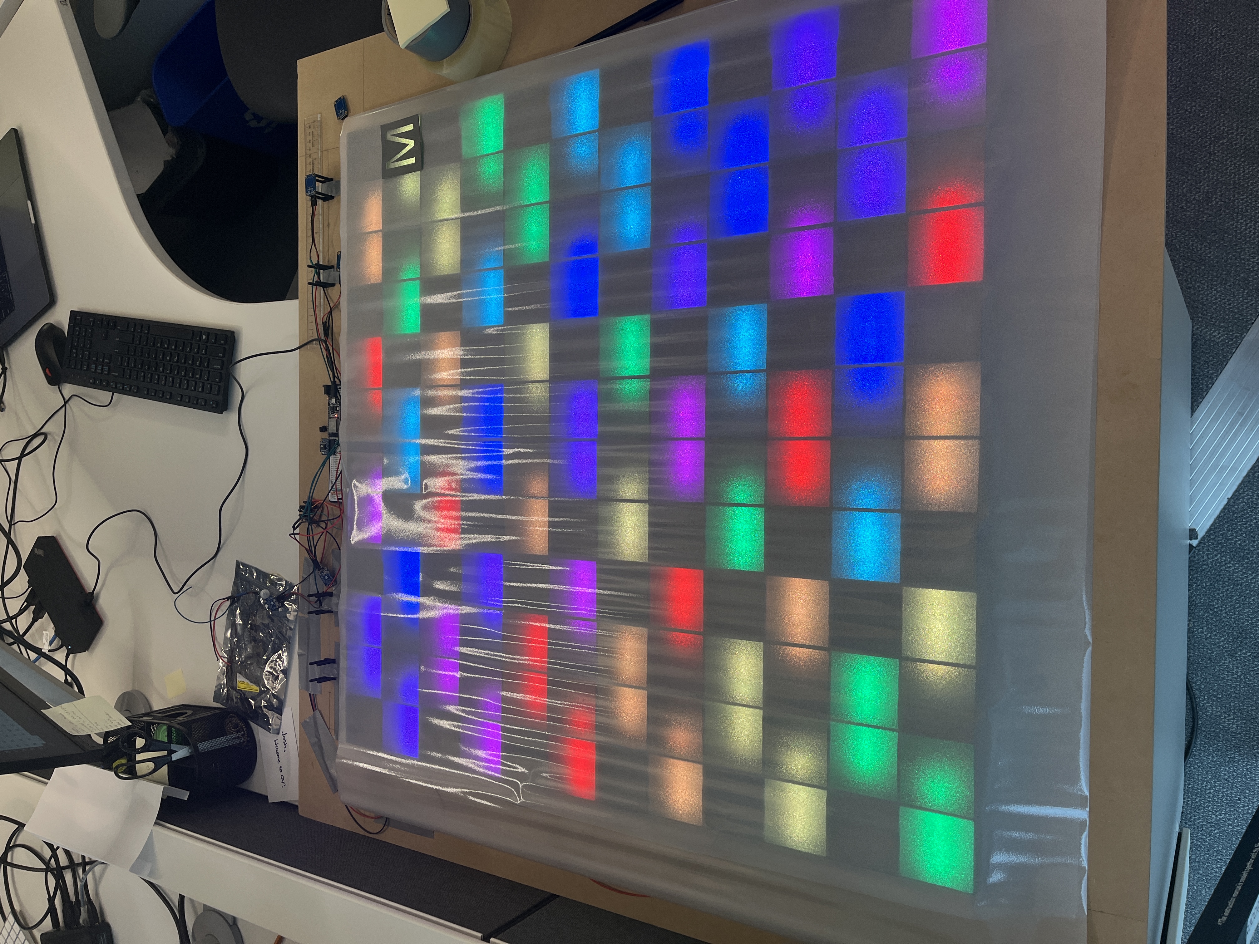
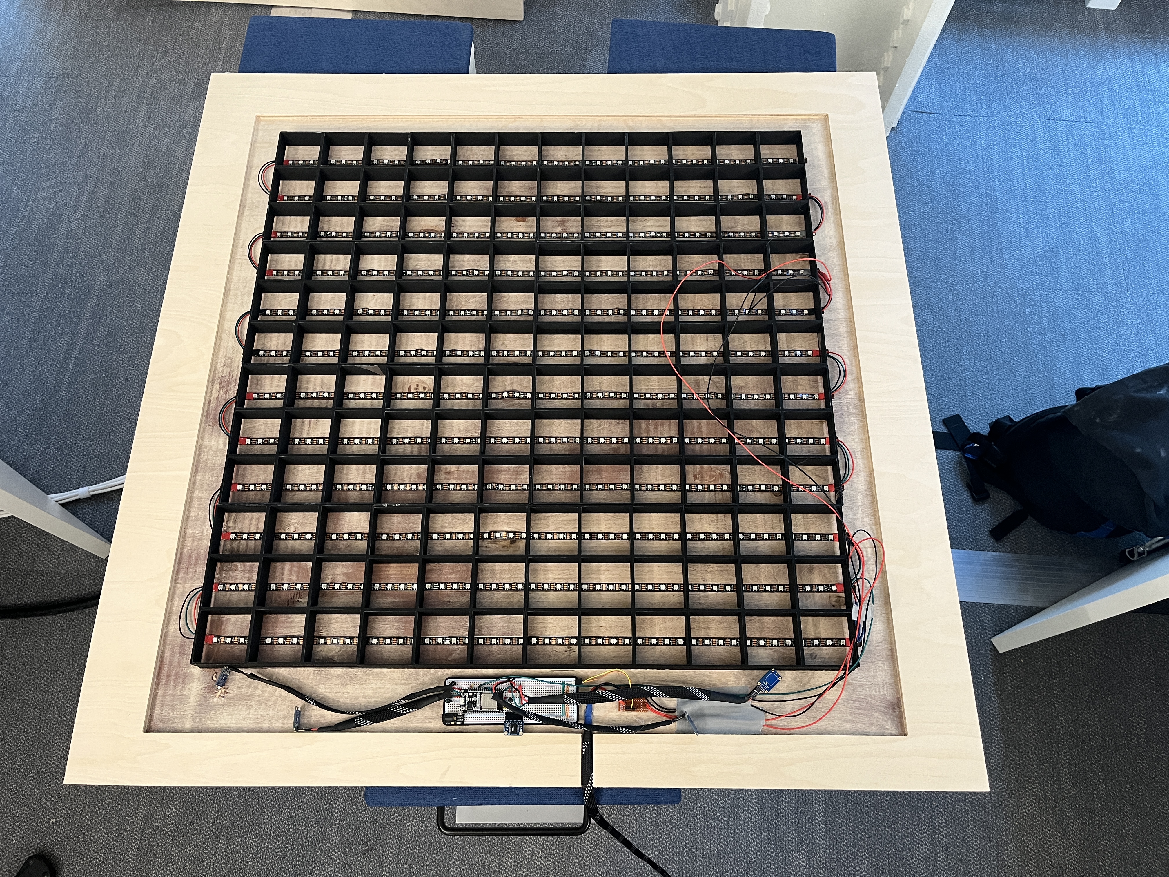
The word clock project's development involved several key steps. The design process began with creating an appealing layout for the LED matrix, with individual LEDs forming the letters required to spell out the time in words. I carefully selected electronic components, such as the RTC for accurate timekeeping and WiFi capabilities for remote configuration. The code was then developed to control the LEDs, manage power consumption, display the time in different formats, and handle user input via capacitive buttons. The project's software also included animations, like a rainbow effect. Moreover, the design incorporated the ability to automatically change clock modes and adjust LED brightness.
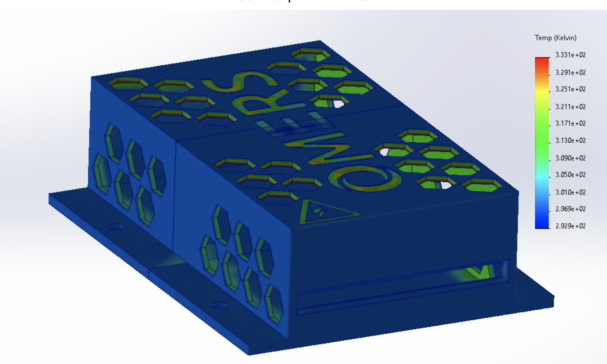
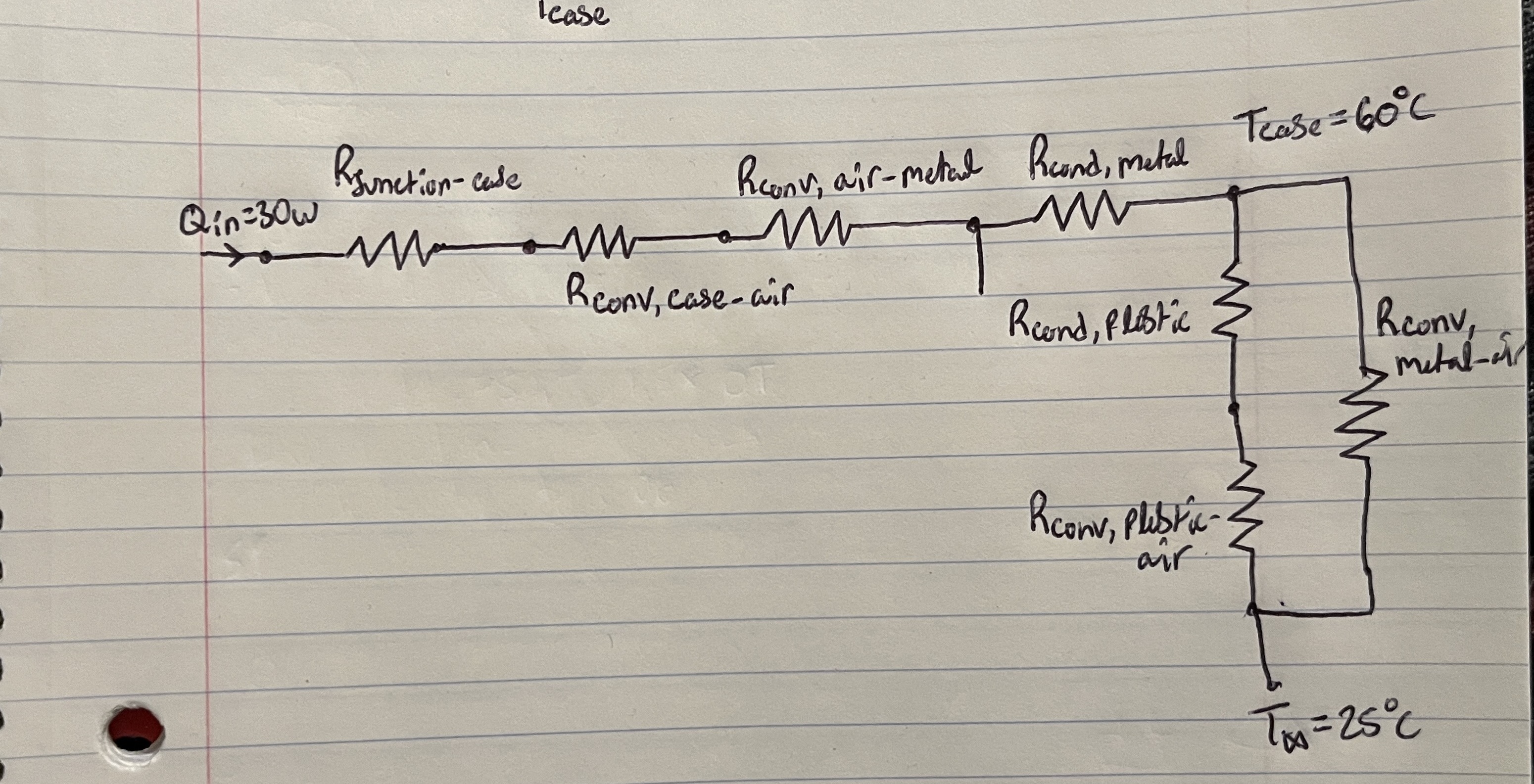
Mechanically, the main body of the word clock is not very complicated. The main body is made out of 3 sheets of plywood held together with bolts from the back of the device. The sheets are laser cut and/or CNC machined, to create channels for the LED's and pockets for the capacitive touch buttons. It uses 3D printed grid pieces recessed into a large rectangular cutout of the lower body panel, as well as rear accessible USB-C port for updated firmware uploads. Something new I got to pick up on was the use of thermal simulations, to analyze the thermal conductivity and heat transfer from the 3D printed PSU housing to ambient surroundings.
The word clock project successfully combines artistry and engineering expertise. The result is an elegant timepiece that not only serves its primary function but also adds a unique visual element to any space. The LED matrix beautifully displays the time in words, providing an engaging and practical way to read the time. The additional features, including LED animations and the ability to display the device's IP address, make the word clock even more functional and visually appealing. Effective power management ensures that the device operates efficiently and is responsive to user interaction. In summary, this mechanical engineering project combines creativity and technical proficiency to deliver a word clock that is both an attractive decoration and a functional timekeeping device.
In totality, the word clock used $800 worth of parts, materials, and machining to create something sold on the market for 15,000+, with a custom flair and personalization for the OMERS office.
Shoe Dryer
Shoe Dryer
Drying Climbing Shoes, learning to lathe, and anodizing.
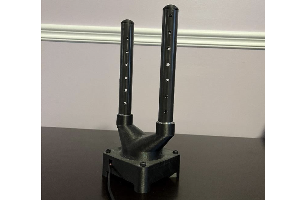
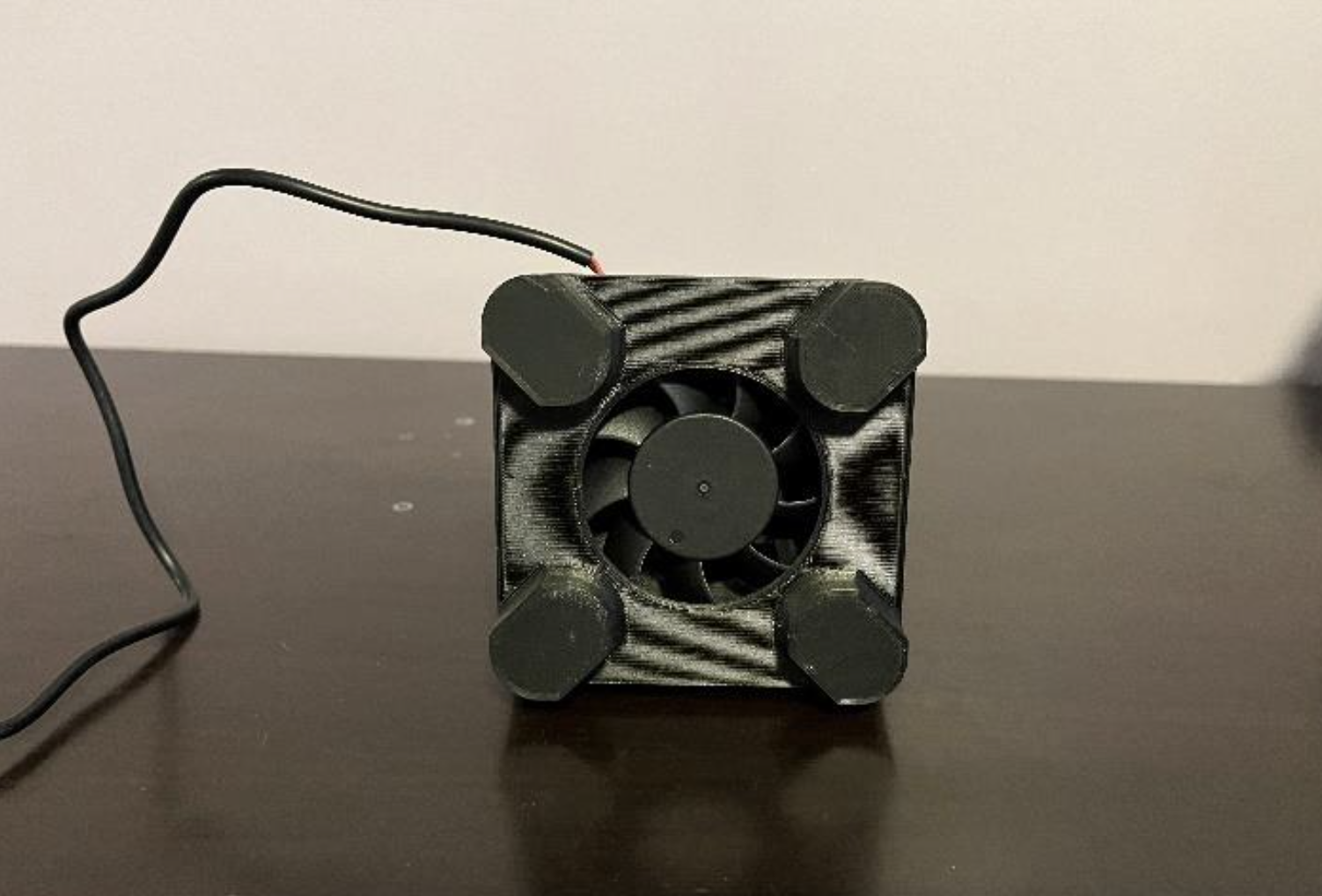
I developed a climbing shoe dryer using a 12 VDC fan, 3D printing, and a lathe to machine Type 1 black anodized aluminum tubes. This included single point threading, precise hole drilling, and boring operations. The dryer is designed to efficiently dry climbing shoes after use, addressing a common issue of moisture buildup, odor, and bacterial growth within the shoes. The climbing shoe dryer provides a convenient and effective solution to enhance the hygiene and longevity of climbing footwear.
I modeled the fan dryer in CAD and used ansys fluent to run air flow simulations. The simulations did not inform much design change, but were just done for the learning experience. The design uses 3D printed female threads to secure the aluminum tubes to the base, and a 2 part base contruction to house the fan.
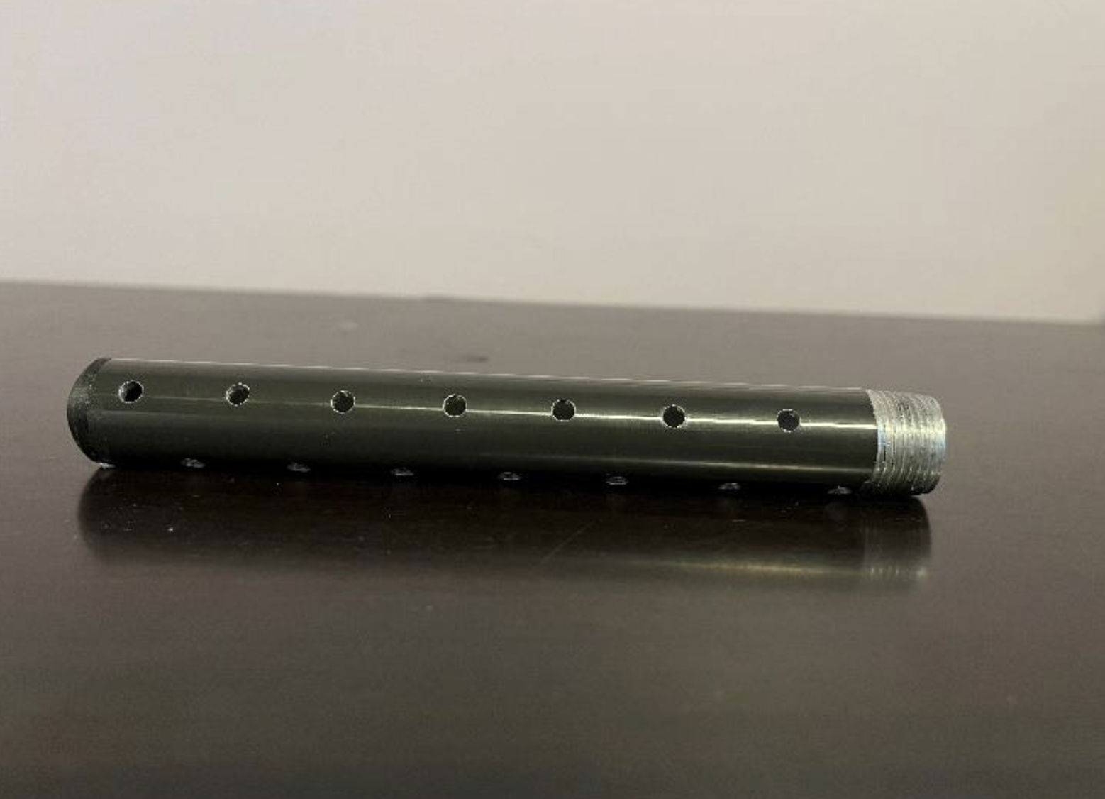
The Aluminum tubes were type 1 anodized black, and then the holes and threads were cut on the lathe.
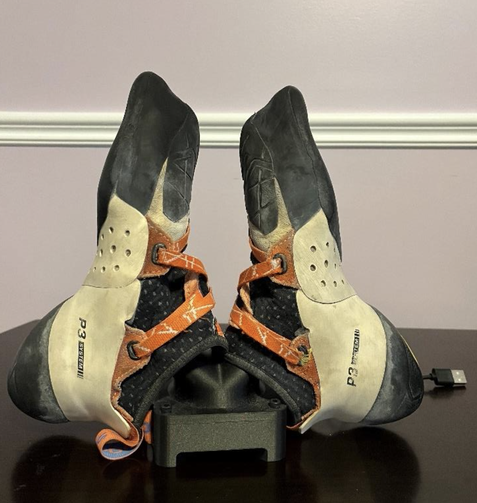
The climbing shoe dryer proved to be highly effective in addressing common shoe hygiene issues, it effectively removes moisture and sweat from climbign shoes, reducing the risk of bacterial growth and foul odors.
By preventing moisture related damage, the dryer helps ectend the lifespan of climbing shoesm ultimately saving climbers money.
The threaded rods can be adjusted to longer or shorter lengths to accomodate all sizes of climbing shoes.
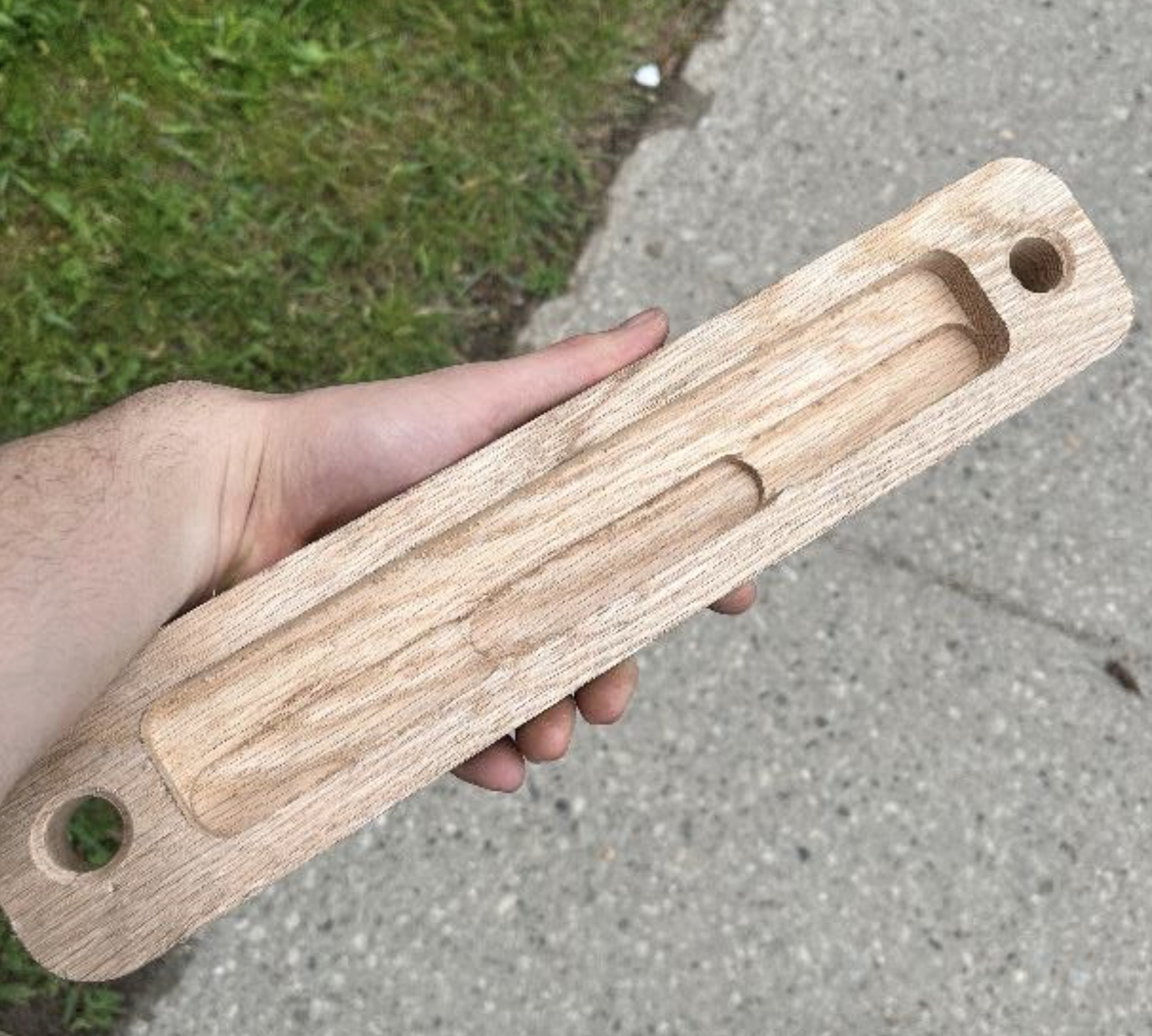
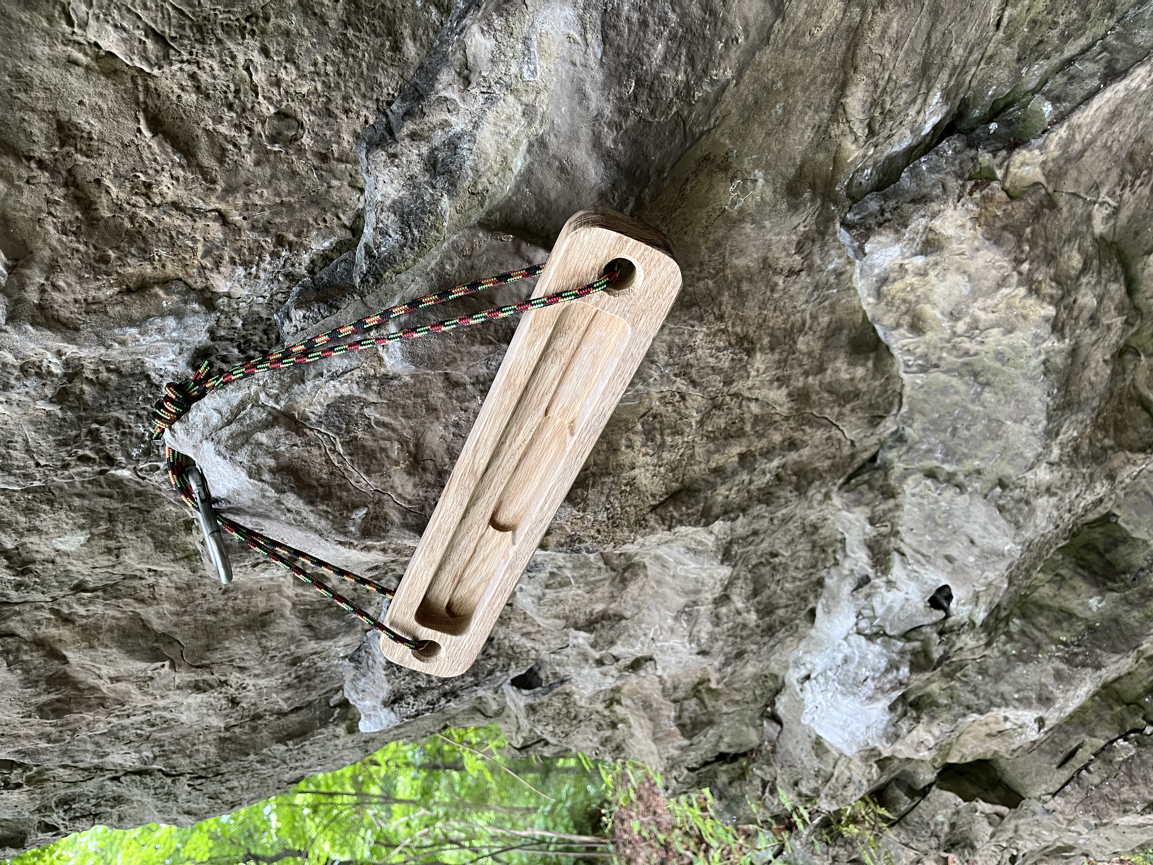
Hangboard
Hangboard
Getting stronger fingers.
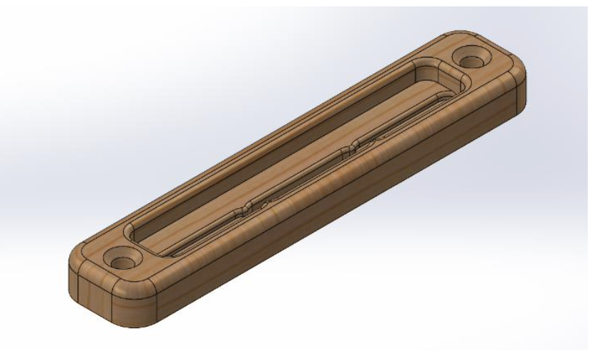
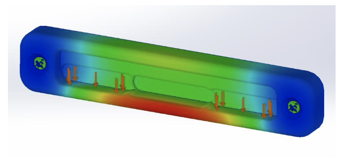
I designed a hangboard in SolidWorks, where I ran static loading FMEAs to confirm factor of safety. I then used SolidWorks CAM to generate a 3 axis CNC process to machine the hangboard. I then took some finishing passes on the mill to bring the back surface to spec.
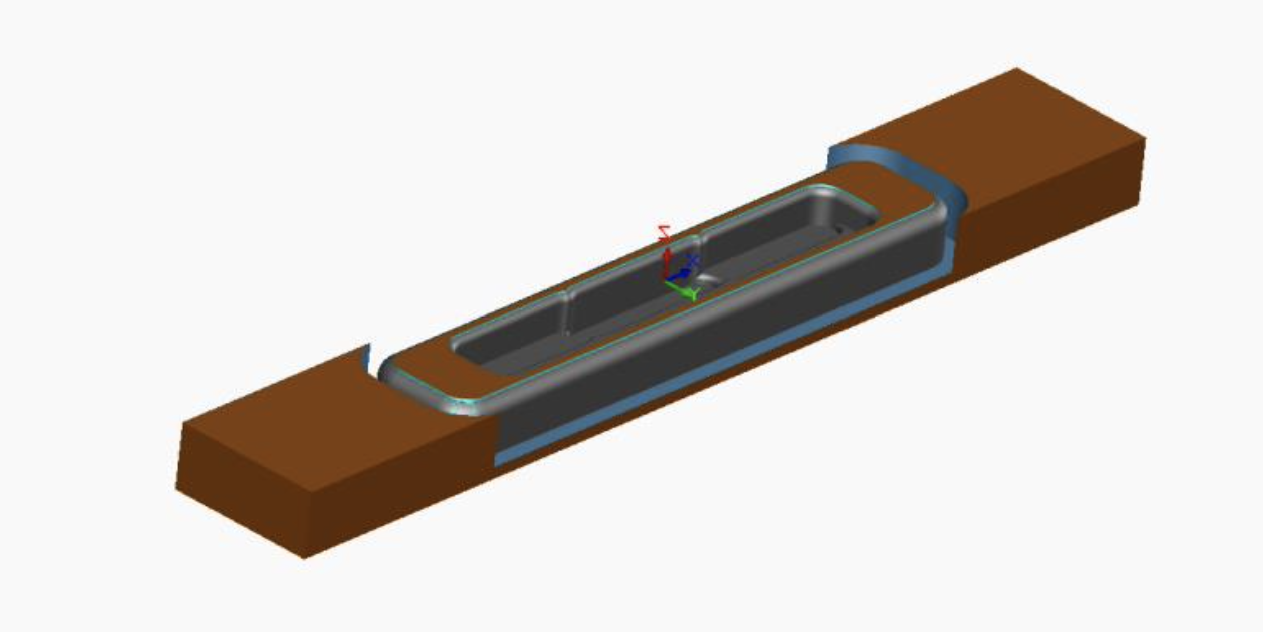
I 3D designed and 3D printed mockups to get the right hold ergonomics (depth, radius, width), before designing the full board with varying edge depths and validating that I can hang with added weight for climbing training. Once the design was complete, I used SolidWorks CAM to select tools, define tool paths, adjust feed and speed parameters, before generating a GCODE file.
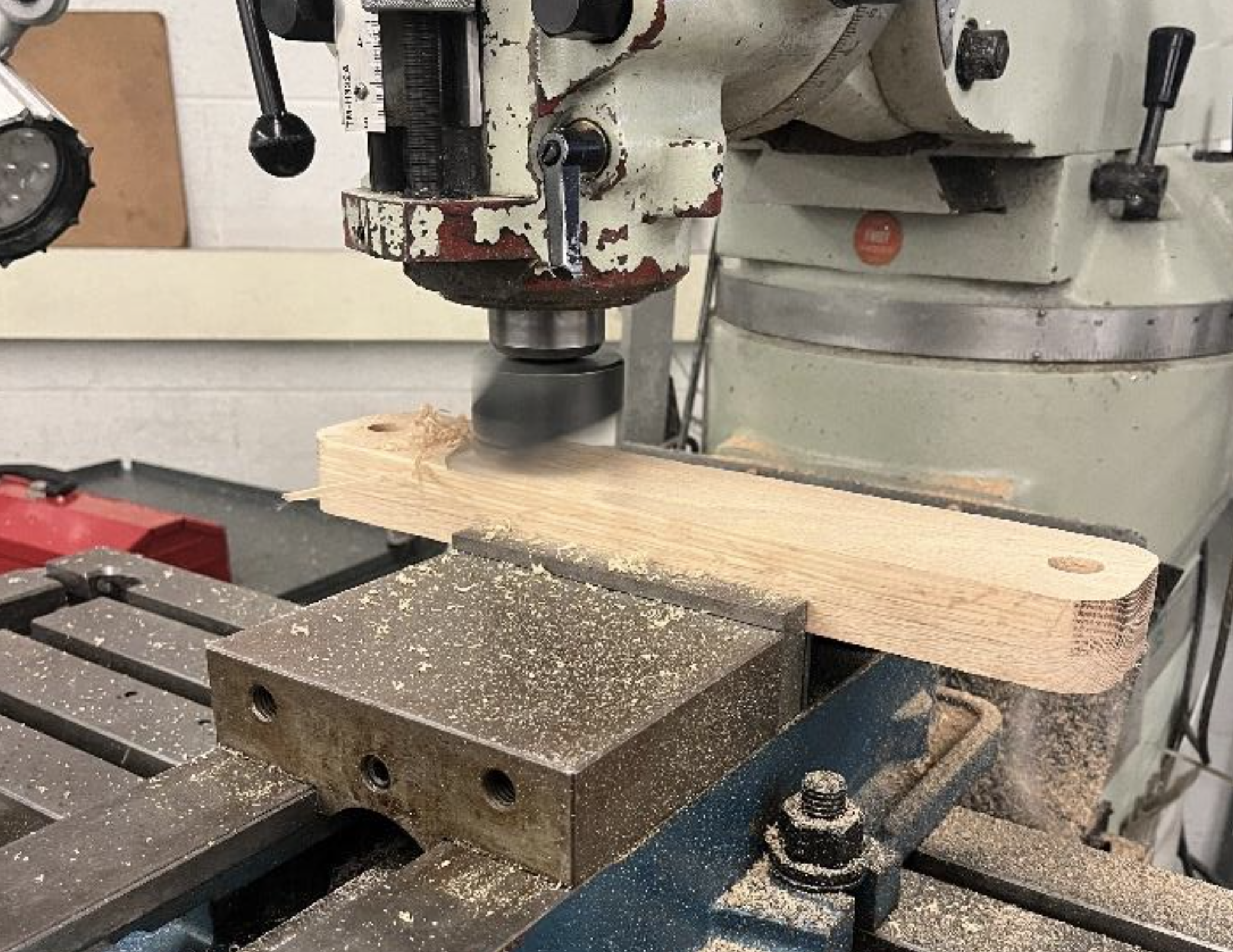
I used a wood planar to square my wood before using a dial indicator to line up the clamps. After the CNC process, I used the mill with a flycutter to bring the back face down to specifications.
The hangboard has comfortably supported my weight plus an additional 100 pounds on the 20mm edge depth. I have used it for the past 2 years everytime I climb outdoors without any failure.
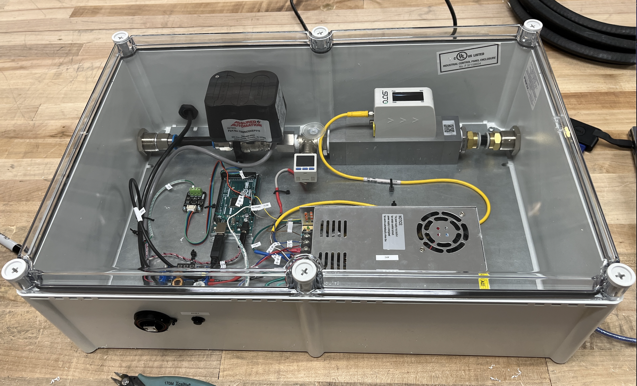
Automated Vacuum Testbench
Automated Vacuum Testbench
Characterizing robot vacuum performance.
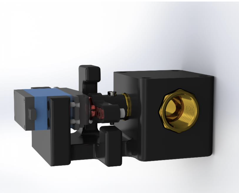
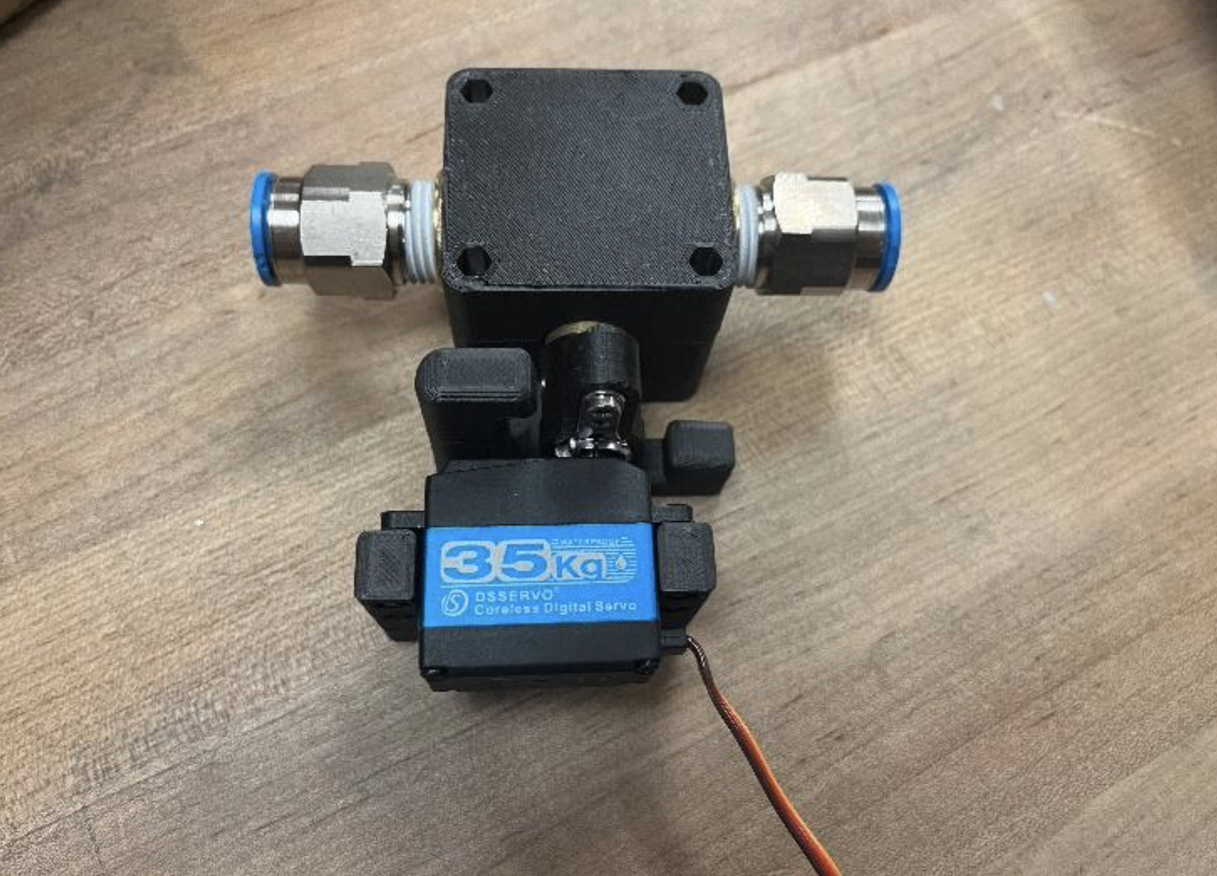
During my work at Kindred AI, I was responsible for making an automated pressure vs flow testbench that measured vacuum pressure and vacuum flow from full vacuum seal to open flow, as a method of evaluating and comparing vacuum generation technologies. As part of this project, there was a need for a ball valve that could have its position be controlled via software.
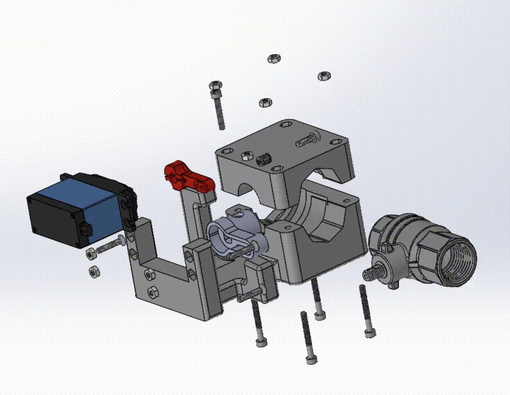
I created a design that uses a servo motor directly driving a 1⁄2” NPT ball valve. Using a Torque wrench, it was determined that the maximum torque required to turn the ball valve was 0.87 NM. A 35 Kg-cm servo motor was used, roughly 4x the required torque. This compensates for angular misalignment and reduces current drawn by the motor.
In the process of designing, other motors and configurations were considered, including gear or belt driven servo motors, or DC hobby motors. However, since it was a requirement that the design require no maintenance, the use of moving or finite life parts was decided against.
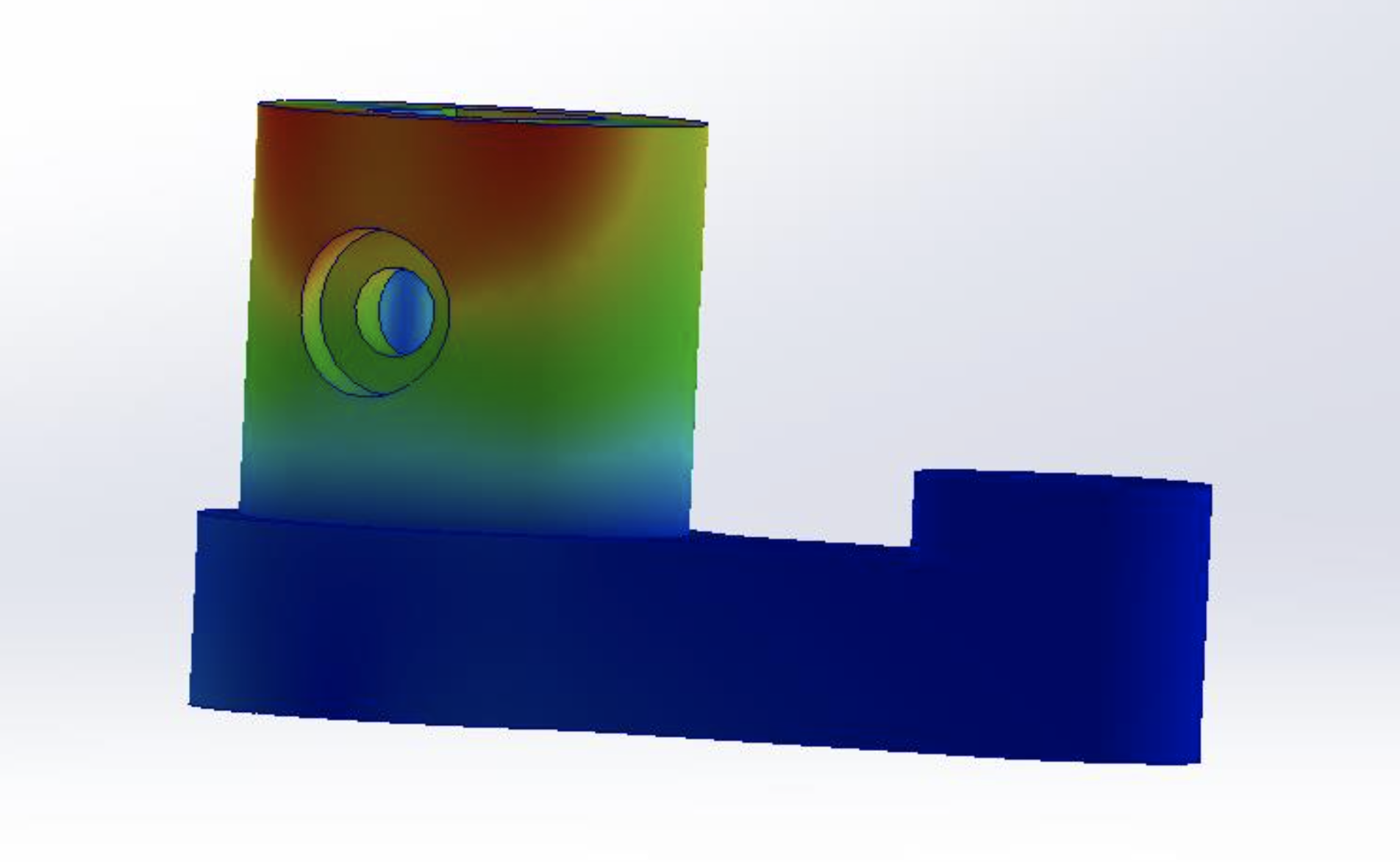
Using the applied torque from the servo motor, an FEA was run to evaluate the angular deformation of the servo arm connector, to calculate the angular dead zone of the 3D printed part. The servo motor is controlled via microstepping and has a resolution of 0.66°.
I reached out to a company that make their own automated ball valves and requested a sample unit that had variable position control and could open/close quick enough to be used for testing. This ball valve ended up being more precise than the servo motor solution I had created, since it can be controlled by the Arduino with a 0-10V DAC (which you can buy with sub milivolt precision).
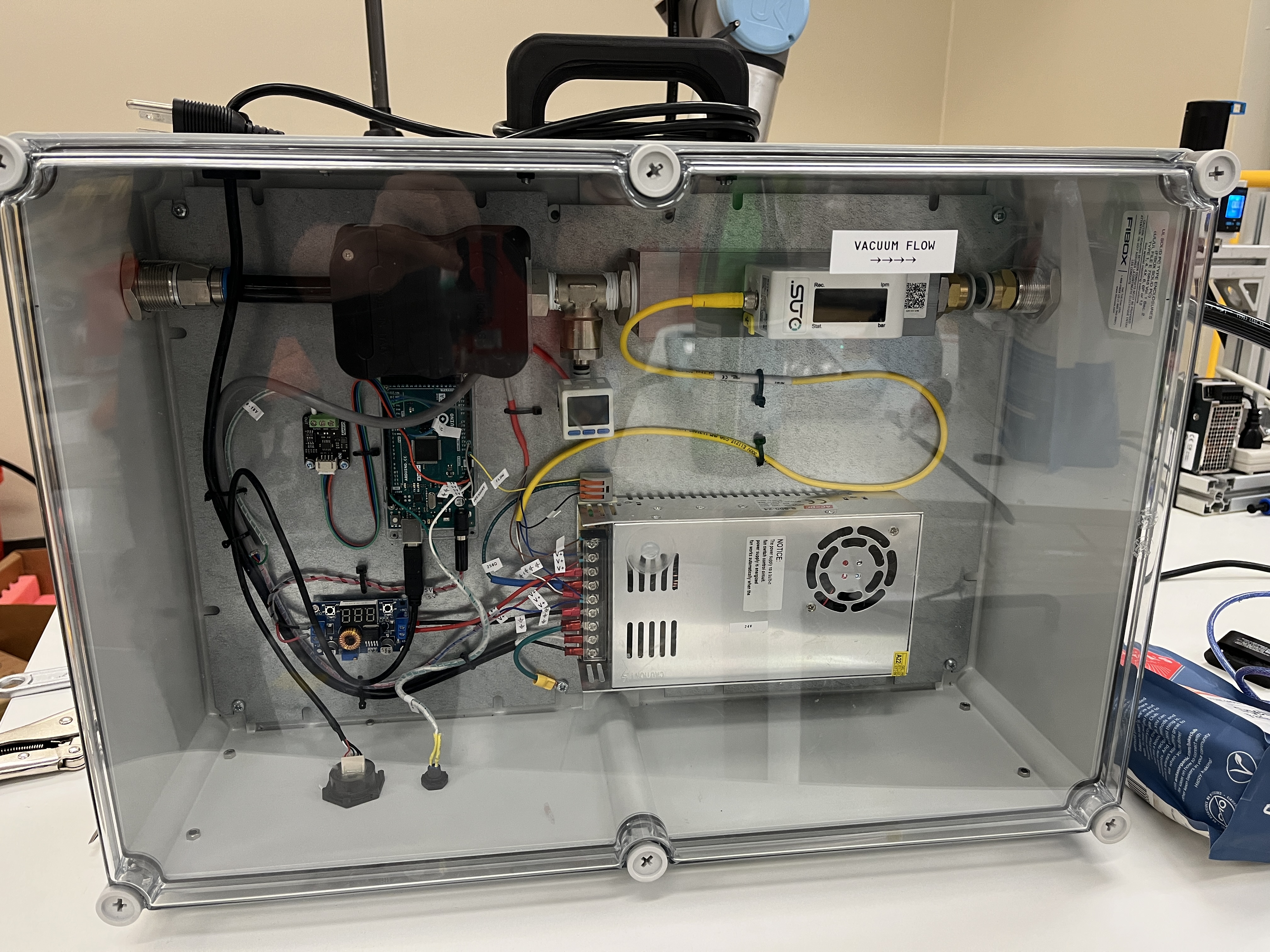
The final automated vaccum testbench is enclosed in a sealed plastic case from McMaster Carr, with a USB female port on the side to communicate with the user. The process of running a test takes 2 minutes, as opposed to 30 minutes manually. The readings are exremely precise, with sub 1% deviation between tests.

Engineering Report
Bi-Wheeled RC Rover
Bi-Wheeled RC Rover
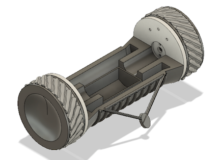
An RC drone modelled after the ones in Rainbow Six Siege.
I decided that I wanted to build a drone similar to that of my favourite video game at the time, Rainbow Six Siege. I used 2 Arduino nano’s with NRF24LO1 modules, and a joystick to control the drone remotely. The remote was created on a custom 2 layer PCB.
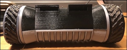
The body of the drone was crafted using PETG (Polyethylene Terephthalate Glycol-modified), a common material used in 3D printing. The choice of PETG was driven by several of its remarkable properties:
Strength and durability:PETG offers a balance of strength and flexibility, which is crucial for a drone body that must withstand a range of operational conditions. This material choice would help the drone withstand minor crashes or impacts without significant damage.
Ease of use:PETG is relatively easy to print with, having less warping and shrinkage than some other materials, such as ABS. This property makes PETG a desirable choice for a complex shape like a drone body.
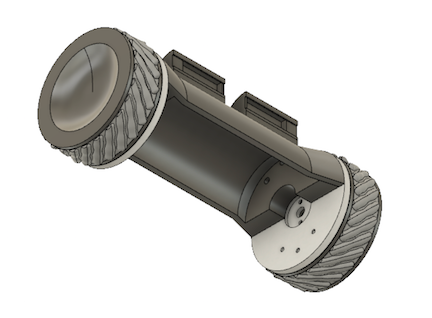
Thermal Stability:Given that drones tend to generate heat due to their internal electronics, PETG's good thermal stability ensures the body won't warp or deform easily during operation. For the wheels of the drone, I chose TPU (Thermoplastic Polyurethane), driven by the need for a material that offered both flexibility and toughness.
Shock Absorption: TPU is highly flexible and can absorb shock well, providing the drone with smoother and more stable movement on various terrains.
Durability:Despite its flexibility, TPU also offers high abrasion resistance and toughness, making it perfect for the drone wheels, which will be continuously subjected to wear and tear.
Flexibility:TPU's flexibility allowed me to design wheels with complex tread patterns, enhancing the drone's ability to navigate challenging terrains.
In terms of the overall shape and configuration of the drone, I aimed to keep true to the aesthetic and functionality of the drone from Rainbow Six Siege, while also incorporating practical aspects related to weight distribution, center of gravity, and overall maneuverability.
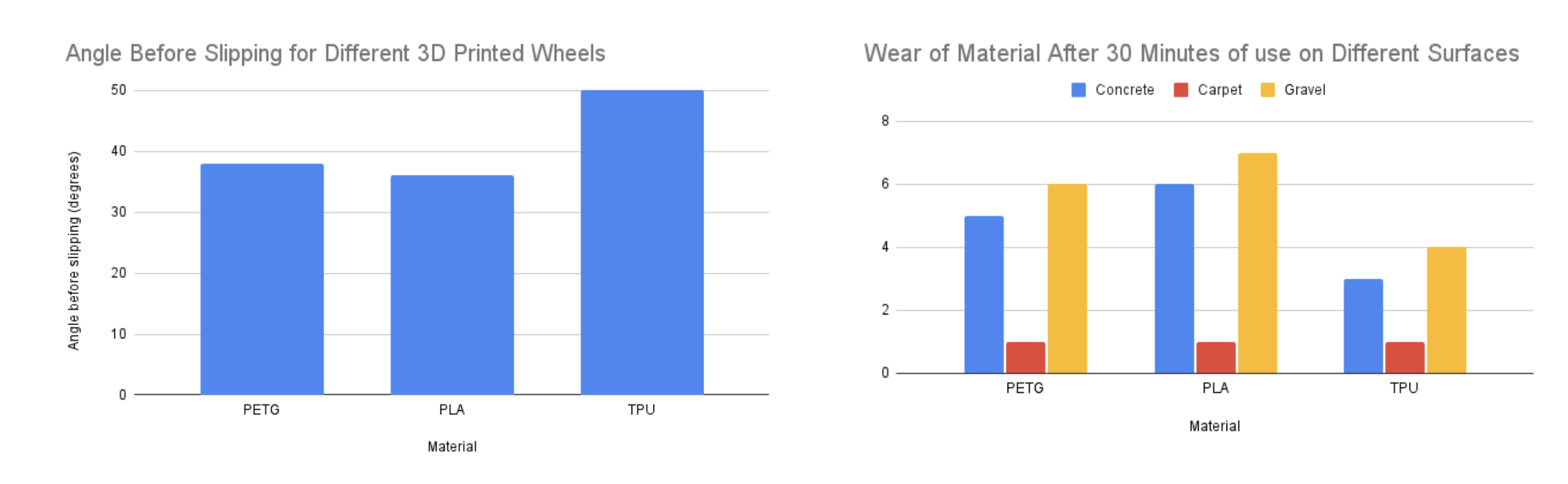
Material Testing:One critical aspect of my project involved comparing the performance of TPU and PETG as material choices for the drone's wheels. The main focus of these tests was to assess the traction and durability of wheels made from each material.
Traction: To evaluate the traction capabilities of both materials, I set up a controlled environment where the drone was made to climb an inclined plane with varying angles. For each test, the angle of incline was increased until the drone wheels started slipping. The maximum angle at which the drone could climb without slipping was recorded for each material. This data served as an indicator of the traction properties of each material.
Durability:For this, I ran the drone with both sets of wheels on different terrains (such as concrete, carpet, and gravel) for a set amount of time, and then evaluated the wear and tear on the wheels. I visually inspected the wheels and recorded any visible wear or damage. The degree of wear served as a measure of the material's durability.
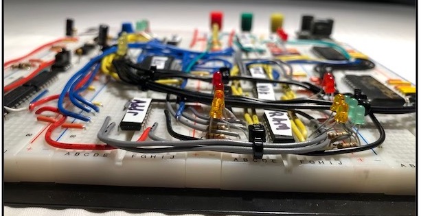
4 Bit Computer
4 Bit Computer
Building a 4 bit computer on a breadboard.
SMD Desktop Equalizer
SMD Desktop Equalizer
Learning SMD Design & Soldering.
Smart Trash Can
Smart Trash Can
An overengineered trash can solution with fill detection and automated garbage disposal.